
Circuit Board Reference Manual

Functional Description
MCF548x Reference Manual, Rev. 3
Freescale Semiconductor 27-31
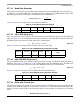
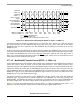
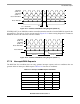
Figure 27-21. Continuous DSPISCK Timing Diagram (CSCK = 0)
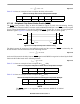
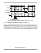
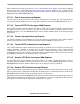
If DTFR[CONT] is set, DSPICSn remains asserted between the transfers when the DSPICSn signal for the
next transfer is the same as for the current transfer. Figure 27-22 shows timing diagram for continuous
DSPISCK format with continuous selection enabled.
Figure 27-22. Continuous DSPISCK Timing Diagram (CSCK = 1)
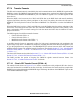
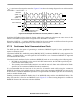
27.7.6 Interrupts/DMA Requests
The DSPI has four conditions that can only generate interrupt requests and two conditions that can
generate either an interrupt or DMA request. Table 27-21 lists the six conditions.
Table 27-21. Interrupt and DMA Request Conditions
Condition Flag Interrupt DMA
End of Queue EOQF X
TX FIFO Fill TFFF X X
Transfer Complete TCF X
TX FIFO Underflow TFUF X
RX FIFO Drain RFDF X X
RX FIFO Overflow RFOF X
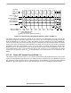
DSPISCK
(CPOL = 0)
PCSS
DSPISCK
(CPOL = 1)
Master DSPISOUT
t
DT
t
DT
= 1 DSPISCK
Master DSPISIN
DSPISCK
(CPOL = 0)
PCSS
DSPISCK
(CPOL = 1)
Master DSPISOUT
Master DSPISIN
Transfer 1 Transfer 2