
Circuit Board Reference Manual

Signal Description
MCF548x Reference Manual, Rev. 3
Freescale Semiconductor 27-3
27.5 Signal Description
27.5.1 Overview
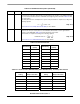
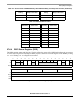
Table 27-1 lists the DSPI signals.
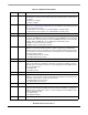
27.5.2 Detailed Signal Descriptions
27.5.2.1 DSPI Peripheral Chip Select/Slave Select (DSPICS0/SS)
In master mode, the DSPICS0 signal is a peripheral chip select output that selects which slave device the
current transmission is intended for.
In slave mode, the SS signal is a slave select input signal that allows an SPI master to select the DSPI as
the target for transmission.
27.5.2.2 DSPI Peripheral Chip Selects 2–3 (DSPICS[2:3])
DSPICS[2:3] are peripheral chip select output signals in master mode. In slave mode these signals are not
used.
27.5.2.3 DSPI Peripheral Chip Select 5/Peripheral Chip Select Strobe
(DSPICS5/PCSS)
When the DSPI is in master mode and the DMCR[PCSSE] bit is cleared, DSPICS5 is used to select the
slave device for which the current transfer is intended DSPICS5 is a peripheral chip select output signal.
PCSS
provides a strobe signal that can be used with an external demultiplexer for deglitching of the n
signals. When the DSPI is in master mode and DMCR[PCSSE] is set, the PCSS provides the appropriate
timing for the decoding of the DSPICS[0,2,3] signals that prevents glitches from occurring.
This signal is not used in slave mode.
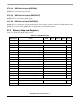
Table 27-1. Signal Properties
Name Input/Output
Function
Master Mode Slave Mode
DSPICS0/SS
Input/Output Peripheral Chip Select 0 (output) Slave Select (input)
DSPICS[2:3] Output Peripheral Chip Select 2 - 3 Unused
DSPICS5/PCSS Output Peripheral Chip Select 5 /
Peripheral Chip Select Strobe
Unused
DSPISIN Input Serial Data In Serial Data In
DSPISOUT Output Serial Data Out Serial Data Out
DSPISCK Input/Output Serial Clock (output) Serial Clock (input)