
Circuit Board Reference Manual

Memory Map/Register Definition
MCF548x Reference Manual, Rev. 3
Freescale Semiconductor 26-21
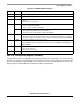
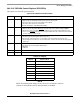
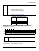
26.3.3.11 Counter Timer Registers (PSCCTURn, PSCCTLRn)
These registers hold the upper and lower bytes of the preload value to be used by the PSC timer in order
to provide a given baud rate.
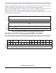
26.3.3.12 Input Port (PSCIPn)
The PSCIP shows the current state of the input ports.
76543210Mode
RCT[15:8]
UART /
SIR
W
R 0 0 0 0 0 0 0 0
All other
modes
W
Reset00000000
Reg
Addr
MBAR + 0x8618 (PSC0); 0x8718 (PSC1); 0x8818 (PSC2); 0x8918 (PSC3)
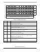
Figure 26-16. Counter Timer Upper Register (PSCCTURn)
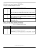
Table 26-15. PSCCTURn Field Descriptions
Bits Name Description
7–0 CT [15:8] PSCCTUR. For UART and SIR modes this field signifies the baud rate prescale value. The
baud rate is calculated as
Baud rate = (system clock frequency) / (CT[15:0] × 16 × 2)
The minimum CT value is 1 and 0 denotes the counter stop.
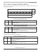
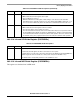
Table 26-16. PSCCTLRn Field Descriptions
Bits Name Description
7–0 CT [7:0] PSCCTLR. For UART and SIR modes this field signifies the baud rate prescale value. The
baud rate is calculated as
Baud rate = (system clock frequency) / (CT[15:0] × 16 × 2)
The minimum CT value is 1 and 0 denotes the counter stop.
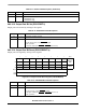
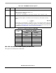
Table 26-17. PSCIPn Field Descriptions
Bits Name Description
7 LPWR_B In UART, IrDA, and modem modes this bit is reserved.
In AC97 mode, this bit signifies the low power mode:
0 CODEC is in low power mode.
1 Usual operation
6 TGL In UART and IrDA modes this bit is reserved.
In AC97 and modem modes, this bit signifies test usage.
Toggle by frame sync.