
Circuit Board Reference Manual

Memory Map/Register Definition
MCF548x Reference Manual, Rev. 3
Freescale Semiconductor 26-17
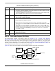
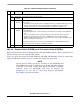
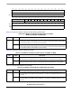
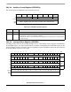
26.3.3.7 Input Port Change Register (PSCIPCRn)
PSCIPCRn shows the current state and the change-of-state for the modem control input port.
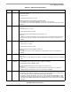
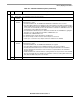
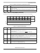
11 SOF Start of frame.
1 RB/TB contains the first sample in the frame. This is also known as the TAG slot. Bits 31–16
contain the valid data
0 RB/TB contains valid data in bits 31–12. This data is not the first sample in a new frame.
10–0 — Reserved, should be cleared.
76543210 Mode
R 0 0 0 D_CTS 1 1 0 CTS UART, SIR,
MIR, FIR
W
R SYNC 0 0 D_CTS 1 1 0 CTS
Modem
W
Reset00001100
Reg
Addr
MBAR + 0x8610 (PSC0); 0x8710 (PSC1); 0x8810 (PSC2); 0x8910 (PSC3)
Figure 26-12. Input Port Change Register (PSCIPCRn)
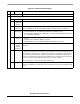
Table 26-11. PSCIPCRn Field Descriptions
Bits Name Description
7 SYNC For UART, SIR, MIR, and FIR modes, this bit is reserved.
For modem modes, this bit signifies Sync is detected or not.
0 Sync not detected.
1 Detected sync (ext_clk=1 in modem8/modem16 or PSC
nRTS=1 in AC97 mode)
6–5 — Reserved, should be cleared.
4 D_CTS Delta CTS
0 No change-of-state has occurred since the last time the CPU read the PSCIPCR. A read of the
PSCIPCR also clears the PSCIPCR D_CTS bit.
1 A change of state, lasting a certain time has occurred at PSCnCTS input. When this bit is set, the
PSCACR can be programmed to generate an interrupt to the processor.
3–2 — Reserved, should be cleared. These bits are set for backward compatibility.
1 — Reserved, should be cleared.
0 CTS Current state of PSCnCTS port. This input is double latched.
0 The current state of the PSCnCTS input port is low.
1 The current state of the PSCnCTS input port is high.
Table 26-10. PSCRBn and PSCTBn AC 97 Mode Field Descriptions
Bits Name Description