
Circuit Board Reference Manual

MCF548x Reference Manual, Rev. 3
21-18 Freescale Semiconductor
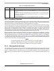
Table 21-10 describes the IMASK fields.
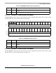
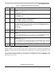
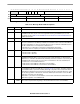
21.3.2.8 Interrupt Flag Register (IFLAG)
IFLAG contains one interrupt flag bit per buffer. Each successful transmission/reception sets the
corresponding IFLAG bit and, if the corresponding IMASK bit is set, will generate an interrupt.
The interrupt flag is cleared by writing a 1. Writing 0 has no effect.
This register contains two 8-bit fields: bits 15–8 (IFLAG_H) and bits 7–0 (IFLAG_L). The register can be
accessed by the master as a 16-bit register, or each byte can be accessed individually using an 8-bit (byte)
access cycle.
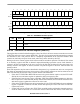
Table 21-12 describes the IFLAG fields.
1514131211109876543210
IMASK_H IMASK_L
RBUF
15M
BUF
14M
BUF
13M
BUF
12M
BUF
11M
BUF
10M
BUF
9M
BUF
8M
BUF7
M
BUF
6M
BUF
5M
BUF
4M
BUF
3M
BUF
2M
BUF
1M
BUF
0M
W
Reset0000000000000000
Reg
Addr
MBAR + 0xA02A (IMASK0); 0xA82A (IMASK1)
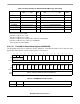
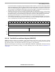
Table 21-9. FlexCAN Interrupt Mask Register (IMASK)
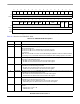
Table 21-10. IMASK Field Descriptions
Bits Name Description
15–0 BUFnM IMASK contains one interrupt mask bit per buffer. It allows the CPU to designate which buffers will
generate interrupts after successful transmission/reception. Each bit enables or disables the
respective FlexCAN message buffer (MB0 to MB15) interrupt.
0 The interrupt for the corresponding buffer is disabled.
1 The interrupt for the corresponding buffer is enabled.
Note: Setting or clearing an IMASK bit can assert or negate an interrupt request, if the
corresponding IFLAG bit it is set.
151141391211109876543210
IFLAG_H IFLAG_L
RBUF
15I
BUF
14I
BUF
13I
BUF
12I
BUF
11I
BUF
10I
BUF
9I
BUF
8I
BUF7
I
BUF
6I
BUF
5I
BUF
4I
BUF
3I
BUF
2I
BUF
1I
BUF
0I
W
Reset0000000000000000
Reg
Addr
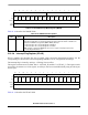
MBAR + 0xA032 (IFLAG0); 0xA832 (IFLAG1)
Table 21-11. FlexCAN Interrupt Flags Register (IFLAG)