
Circuit Board Reference Manual

Memory Map/Register Definition
MCF548x Reference Manual, Rev. 3
Freescale Semiconductor 14-3
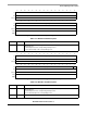
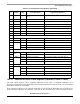
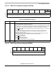
14.3.2.1 EPORT Pin Assignment Register (EPPAR)
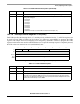
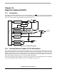
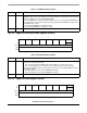
14.3.2.2 EPORT Data Direction Register (EPDDR)
1514131211109876543210
R EPPA7 EPPA6 EPPA5 EPPA4 EPPA3 EPPA2 EPPA1 0 0
W
Reset0000000000000000
Reg
Addr
MBAR + 0xF00
Figure 14-2. EPORT Pin Assignment Register (EPPAR)
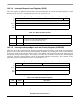
Table 14-2. EPPAR Field Descriptions
Bits Name Description
15–2 EPPAn EPORT pin assignment select fields. The read/write EPPAn fields configure EPORT pins for level
detection and rising and/or falling edge detection.
Pins configured as level-sensitive are inverted so that a logic 0 on the external pin represents a valid
interrupt request. Level-sensitive interrupt inputs are not latched. To guarantee that a level-sensitive
interrupt request is acknowledged, the interrupt source must keep the signal asserted until
acknowledged by software. Level sensitivity must be selected to bring the device out of stop mode
with an IRQ
n interrupt.
Pins configured as edge-triggered are latched and need not remain asserted for interrupt
generation. A pin configured for edge detection can trigger an interrupt regardless of its
configuration as input or output.
Interrupt requests generated in the EPORT module can be masked by the interrupt controller
module. EPPAR functionality is independent of the selected pin direction.
Reset clears the EPPAn fields.
00 Pin IRQ
n level-sensitive
01 Pin IRQn rising edge triggered
10 Pin IRQ
n falling edge triggered
11 Pin IRQn both falling edge and rising edge triggered
1–0 — Reserved, should be cleared.
76543210
R EPDD7 EPDD6 EPDD5 EPDD4 EPDD3 EPDD2 EPDD1 0
W
Reset00000000
Reg
Addr
MBAR + 0xF04
Figure 14-3. EPORT Data Direction Register (EPDDR)