
Circuit Board Reference Manual

MCF548x Reference Manual, Rev. 3
8-60 Freescale Semiconductor
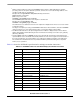
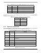
Depending on the size of any external memory operand specified by the f<op>.fmt field, the data marker
is defined as shown in Table 8-33.
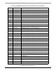
8.7.2 Supervisor Instruction Set
The supervisor instruction set has complete access to the user mode instructions plus the opcodes shown
below. The PSTDDATA specification for these opcodes is shown in Table 8-34.
fneg.sz <ea>y,FPx PSTDDATA = 0x1, [89B], source}
fnop PSTDDATA = 0x1
fsqrt.sz <ea>y,FPx PSTDDATA = 0x1, [89B], source}
fsub.sz <ea>y,FPx PSTDDATA = 0x1, [89B], source}
ftst.sz <ea>y PSTDDATA = 0x1, [89B], source}
1
The FP*R notation refers to the floating-point control registers: FPCR, FPSR, and FPIAR.
Table 8-33. Data Markers and FPU Operand Format Specifiers
Format Specifier Data Marker
.b 8
.w 9
.l B
.s B
.d Never captured
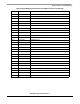
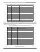
Table 8-34. PSTDDATA Specification for Supervisor-Mode Instructions
Instruction Operand Syntax PSTDDATA
cpushl dc,(Ax)
ic,(Ax)
bc,(Ax)
PSTDDATA = 0x1
frestore <ea>y PSTDDATA = 0x1
fsave <ea>x PSTDDATA = 0x1
halt PSTDDATA = 0x1,
PSTDDATA = 0xF
intouch (Ay) PSTDDATA = 0x1
move.l Ay,USP PSTDDATA = 0x1
move.l USP,Ax PSTDDATA = 0x1
move.w SR,Dx PSTDDATA = 0x1
move.w {Dy,#<data>},SR PSTDDATA = 0x1, {0x3}
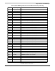
Table 8-32. PSTDDATA Values for User-Mode Floating-Point Instructions (Continued)
Instruction
1
Operand Syntax PSTDDATA