
Microcontrollers Data Sheet


Timer Interface B (TIMB)
MC68HC908MR32 • MC68HC908MR16 Data Sheet, Rev. 6.1
238 Freescale Semiconductor
17.3.1 TIMB Counter Prescaler
The TIMB clock source can be one of the seven prescaler outputs or the TIMB clock pin, PTE0/TCLKB.
The prescaler generates seven clock rates from the internal bus clock. The prescaler select bits, PS[2:0],
in the TIMB status and control register select the TIMB clock source.
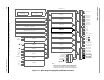
17.3.2 Input Capture
An input capture function has three basic parts:
1. Edge select logic
2. Input capture latch
3. 16-bit counter
Two 8-bit registers, which make up the 16-bit input capture register, are used to latch the value of the
free-running counter after the corresponding input capture edge detector senses a defined transition. The
polarity of the active edge is programmable. The level transition which triggers the counter transfer is
defined by the corresponding input edge bits (ELSxB and ELSxA in TBSC0–TBSC1 control registers with
x referring to the active channel number). When an active edge occurs on the pin of an input capture
channel, the TIMB latches the contents of the TIMB counter into the TIMB channel registers,
TCHxH–TCHxL. Input captures can generate TIMB CPU interrupt requests. Software can determine that
an input capture event has occurred by enabling input capture interrupts or by polling the status flag bit.
The free-running counter contents are transferred to the TIMB channel status and control register
(TBCHxH–TBCHxL, see 17.7.5 TIMB Channel Registers) on each proper signal transition regardless of
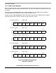
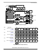
$0056
TIMB Channel 0 Status/Control
Register
(TBSC0) See page 247.
Read: CH0F
CH0IE MS0B MS0A ELS0B ELS0A TOV0 CH0MAX
Write: 0
Reset: 0 0 0 0 0 0 0 0
$0057
TIMB Channel 0 Register High
(TBCH0H)
See page 250.
Read:
Bit 15 Bit 14 Bit 13 Bit 12 Bit 11 Bit 10 Bit 9 Bit 8
Write:
Reset: Indeterminate after reset
$0058
TIMB Channel 0 Register Low
(TBCH0L)
See page 250.
Read:
Bit 7 Bit 6 Bit 5 Bit 4 Bit 3 Bit 2 Bit 1 Bit 0
Write:
Reset: Indeterminate after reset
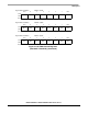
$0059
TIMB Channel 1 Status/Control
Register
(TBSC1) See page 247.
Read: CH1F
CH1IE
0
MS1A ELS1B ELS1A TOV1 CH1MAX
Write: 0 R
Reset: 0 0 0 0 0 0 0 0
$005A
TIMB Channel 1 Register High
(TBCH1H)
See page 250.
Read:
Bit 15 Bit 14 Bit 13 Bit 12 Bit 11 Bit 10 Bit 9 Bit 8
Write:
Reset: Indeterminate after reset
$005B
TIMB Channel 1 Register Low
(TBCH1L)
See page 250.
Read:
Bit 7 Bit 6 Bit 5 Bit 4 Bit 3 Bit 2 Bit 1 Bit 0
Write:
Reset: Indeterminate after reset
Addr. Register Name Bit 7 6 5 4 3 2 1 Bit 0
R= Reserved
Figure 17-3. TIMB I/O Register Summary (Continued)