
Microcontrollers Data Sheet


Advance Information MC68HC(7)08KH12 — Rev. 1.1
62 Freescale Semiconductor
7.7 Low-Power Modes . . . . . . . . . . . . . . . . . . . . . . . . . . . . . . . . . .79
7.7.1 Wait Mode . . . . . . . . . . . . . . . . . . . . . . . . . . . . . . . . . . . . . .80
7.7.2 Stop Mode. . . . . . . . . . . . . . . . . . . . . . . . . . . . . . . . . . . . . .81
7.8 SIM Registers . . . . . . . . . . . . . . . . . . . . . . . . . . . . . . . . . . . . . .83
7.8.1 Break Status Register (BSR). . . . . . . . . . . . . . . . . . . . . . . .83
7.8.2 Reset Status Register (RSR) . . . . . . . . . . . . . . . . . . . . . . .84
7.8.3 Break Flag Control Register (BFCR). . . . . . . . . . . . . . . . . .85
7.2 Introduction
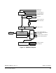
This section describes the system integration module (SIM), which
supports up to 24 external and/or internal interrupts. Together with the
CPU, the SIM controls all MCU activities. A block diagram of the SIM is
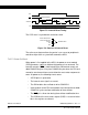
shown in Figure 7-1. Figure 7-2 is a summary of the SIM I/O registers.
The SIM is a system state controller that coordinates CPU and exception
timing. The SIM is responsible for:
• Bus clock generation and control for CPU and peripherals
– top/wait/reset/break entry and recovery
– Internal clock control
• Master reset control, including power-on reset (POR) and COP
timeout
• Interrupt control:
– Acknowledge timing
– Arbitration control timing
– Vector address generation
• CPU enable/disable timing
• Modular architecture expandable to 128 interrupt sources