
Microcontrollers Data Sheet


MC68HC(7)08KH12 — Rev. 1.1 Advance Information
Freescale Semiconductor
255
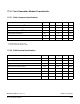
17.12 HUB Repeater Electrical Characteristics
Low Speed HUB Electrical Characteristics (Root port and downstream ports configured as low speed)
Characteristic Symbol
Conditions
(Notes 1,2,3)
Min Typ Max Unit
HUB Differential Data Delay TLHDD Note 4, 7, 8 300 ns
HUB Differential Driver Jitter
(including cable)
Downstream:
To Next Transition
For Paired Transitions
Upstream
To Next Transition
For Paired Transitions
T
LDHJ1
T
LDHJ2
T
LUHJ1
T
LUHJ2
Note 4, 7, 8
–45
–15
45
45
45
15
45
45
ns
ns
ns
ns
Data bit width distortion after EOP. TSOP Note 4,8 –60 60 ns
HUB EOP Delay Relative to T
HDD
TLEOPD Note 4,8 0 200 ns
HUB EOP Output Width Skew TLHESK Note 4,8 –300 300 ns
Full Speed HUB Electrical Characteristics (Root port and downstream ports configured as full speed)
Characteristic Symbol
Conditions
(Notes 1,2,3)
Min Typ Max Unit
HUB Differential Data Delay
(with cable)
(without cable)
T
HDD1
T
HDD1
Note 3, 7, 8 70
40
ns
ns
HUB Differential Driver Jitter
(including cable)
To Next Transition
For Paired Transitions
T
HDJ1
T
HDJ2
Note 3, 7, 8
–3
–1
3
1
ns
ns
Data bit width distortion after SOP. T
SOP
Note 3, 8 –5 5 ns
HUB EOP Delay Relative to T
HDD
T
EOPD
Note 3, 8 0 15 ns
HUB EOP Output Width Skew T
HESK
Note 3, 8 –15 15 ns
NOTES:
1. All voltages measured from local ground, unless otherwise specified.
2. All timings use a capacitive load of (CL) to ground of 50pF, unless otherwise specified.
3. Full speed timings have a 1.5kΩ pull-up to 2.8V on the D+ data line.
4. Low speed timings have a 1.5kΩ pull-up to 2.8V on the D– data line.
5. Measured from 10% to 90% of the data signal.
6. The rising and falling edges should be smoothly transitioning (monotonic).
7. Timing differences between the differential data signals.
8. Measured at crossover point of differential data signals.
9. The maximum load specification is the maximum effective capacitive load allowed that meets the target HUB VBUS droop of 330mV.