
Microcontrollers Data Sheet


MC68HC(7)08KH12 — Rev. 1.1 Advance Information
Freescale Semiconductor
211
COPRS — COP Rate Select Bit
COPRS selects the COP timeout period. Reset clears COPRS.
1 = COP reset cycle is (2
13
–2
4
)×CGMXCLK
0 = COP reset cycle is (2
18
–2
4
)×CGMXCLK
COPD — COP Disable Bit
COPD disables the COP module.
1 = COP module disabled
0 = COP module enabled
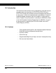
13.5 COP Control Register (COPCTL)
The COP control register is located at address $FFFF and overlaps the
reset vector. Writing any value to $FFFF clears the COP counter and
starts a new timeout period. Reading location $FFFF returns the low
byte of the reset vector.
13.6 Interrupts
The COP does not generate CPU interrupt requests.
13.7 Monitor Mode
The COP is disabled in monitor mode when V
DD
+V
HI
is present on the
IRQ1
/V
PP
pin or on the RST pin.
Address: $FFFF
Bit 7654321Bit 0
Read: Low byte of reset vector
Write: Clear COP counter
Reset: Unaffected by reset
Figure 13-3. COP Control Register (COPCTL)