
Microcontrollers Data Sheet


Advance Information MC68HC(7)08KH12 — Rev. 1.1
208 Freescale Semiconductor
13.3 Functional Description
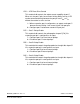
Figure 13-1 shows the structure of the COP module.
Figure 13-1. COP Block Diagram
COPCTL WRITE
CGMXCLK
RESET VECTOR FETCH
RESET CIRCUIT
RESET STATUS REGISTER
INTERNAL RESET SOURCES
12-BIT SIM COUNTER
CLEAR ALL STAGES
6-BIT COP COUNTER
COP DISABLE
RESET
COPCTL WRITE
CLEAR
COP MODULE
COPEN (FROM SIM)
COP COUNTER
COP CLOCK
COP TIMEOUT
STOP INSTRUCTION
(COPD FROM CONFIG)
COP RATE SEL
(COPRS FROM CONFIG)
CLEAR STAGES 5–12
Table 13-1. COP I/O Port Register Summary
Addr. Register Name Bit 7 6 5 4 3 2 1 Bit 0
$001F
Configuration Register
(CONFIG)
†
Read: 0000
SSREC COPRS STOP COPD
Write:
Reset:00000000
$FFFF
COP Control Register
(COPCTL)
Read: Low byte of reset vector
Write: Clear COP counter
Reset: Unaffected by reset
† One-time writable register
= Unimplemented