3StackQS_WinCE.book Page 1 Friday, November 21, 2008 11:46 AM i.MX27 PDK 1.0 Windows Embedded CE 6.
3StackQS_WinCE.book Page 2 Friday, November 21, 2008 11:46 AM Information in this document is provided solely to enable system and software implementers to use Freescale Semiconductor products. There are no express or implied copyright licenses granted hereunder to design or fabricate any integrated circuits or integrated circuits based on the information in this document. Freescale Semiconductor reserves the right to make changes without further notice to any products herein.
StackQS_WinCE.book Page 1 Friday, November 21, 2008 11:46 AM 1 About the Boards 3 About the 3-Stack Platform System . . . . . . . . . . . . . . . . . . . . . . . . . . . . . . . . . . . 3 CPU Board . . . . . . . . . . . . . . . . . . . . . . . . . . . . . . . . . . . . . . . . . . . . . . . . . . . . . . 7 Debug Board . . . . . . . . . . . . . . . . . . . . . . . . . . . . . . . . . . . . . . . . . . . . . . . . . . . . . 8 Personality Board . . . . . . . . . . . . . . . . . . . . . . . . . . . . . . .
3StackQS_WinCE.book Page 2 Friday, November 21, 2008 11:46 AM i.MX27 PDK 1.
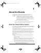
3StackQS_WinCE.book Page 3 Friday, November 21, 2008 11:46 AM 1 About the Boards This chapter provides detailed information about the three boards (CPU, Debug, Personality) and the locations of the connectors and switches for each. CAUTION Your PDK arrives housed in a plastic device enclosure, which under normal circumstances you should not remove.
3StackQS_WinCE.book Page 4 Friday, November 21, 2008 11:46 AM About the Boards About the 3-Stack Platform System common multimedia applications, and has a 2.8-inch VGA display, image sensor camera, Wi-Fi CERTIFIED™ IEEE 802.11™ b/g standards, FM receiver, SD Card connector, USB OTG, USB Host, 2.4 QVGA smart display panel connector, ATA connector and TV-Out connector. As the 3-Stack platform continues to evolve, more Personality boards will be created to meet new multimedia requirements. Table 1.
3StackQS_WinCE.book Page 5 Friday, November 21, 2008 11:46 AM About the Boards About the 3-Stack Platform System Table 1.
3StackQS_WinCE.book Page 6 Friday, November 21, 2008 11:46 AM About the Boards About the 3-Stack Platform System Table 1.1 3-Stack Platform Features Details Cables • 5.0V/2.
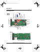
3StackQS_WinCE.book Page 7 Friday, November 21, 2008 11:46 AM About the Boards CPU Board CPU Board CPU Board Top Bottom J1 Board-to-Board Connector Figure 1.1 CPU Board You use the J1 board-to-board connector (500 pins) to connect the CPU board to either of the other two boards: • Connect the CPU board to a Personality board, for running demos (no Debug board is needed). • Connect the CPU board to a Debug board, (and connect the Personality board to the Debug board) for developing software.
3StackQS_WinCE.book Page 8 Friday, November 21, 2008 11:46 AM About the Boards Debug Board To Personality Board Connector CN74 DC Power LED D11 Power-On S4 Resettable Fuse F1 3.3V LED D9 SW5–SW10 See Table 1.4 CPLD LEDs D1– TOP MX27 JTAG CN1 SW4 See Table 1.
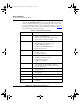
3StackQS_WinCE.book Page 9 Friday, November 21, 2008 11:46 AM About the Boards Debug Board Table 1.2 Debug Board Physical Features Type Physical Feature Switches • S1: Power button • S2: Debug board reset button • S3: System reset switch • S4: Power-on switch • SW4: Enable switch Connectors • J1:10/100 Base-T Ethernet RJ45 connector • J2: 5.
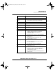
3StackQS_WinCE.book Page 10 Friday, November 21, 2008 11:46 AM About the Boards Debug Board Table 1.3 Debug Board SW4 Switch Switch Setting Effect SW4-1 UART Port Select ON Selects serial port UART (DCE) CON4 SW4-8 Power Enable ON Power is supplied to all three boards. OFF Power is only supplied to the Debug board. Table 1.
3StackQS_WinCE.
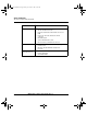
3StackQS_WinCE.book Page 12 Friday, November 21, 2008 11:46 AM About the Boards Personality Board Table 1.5 Personality Board Physical Features Type Physical Feature Connectors • CN12: 44-position dual row, 2 mm header for HDD • CN13: GPS module connector • CN14: 2.
3StackQS_WinCE.book Page 13 Friday, November 21, 2008 11:46 AM 2 Getting Started Unpack the Kit The 3-Stack Platform System is shipped with the items listed in Table 2.1. Table 2.1 Contents Type Items Boards • CPU board • Debug board • Personality board Cables • RS-232 serial cable • Ethernet straight cable • High-speed USB cables with mini AB connectors for OTG • High-speed cable with standard A to mini B connectors • Mini-USB adaptor • Jack to RCA audio/video cable Power Supply • 5.0V/2.
3StackQS_WinCE.book Page 14 Friday, November 21, 2008 11:46 AM Getting Started Unpack the Kit CD-ROM RS-232 Ethernet Straight Cable Mini-AB USB OTG A to Mini-B USB Cable A to Mini B USB Cable Universal Power Supply CPU Board Debug Board Personality Board Jack to RCA Audio/Video Cable Figure 2.1 PDK Kit Contents i.MX27 PDK 1.0 Quick Start Guide, Rev. 1.
3StackQS_WinCE.book Page 15 Friday, November 21, 2008 11:46 AM Getting Started CD-ROM Contents CD-ROM Contents Table 2.2.identifies the items on the CD-ROM set. Table 2.2 Development PC Requirements Type Requirement Product Documentation • i.MX27 PDK Product Brief • Bill of Materials, Schematics, and Gerber files for • CPU Board, Personality Board, and Debug Board • i.MX27 Demo Image Readme Windows Embedded CE 6.0 • i.MX Platform Hardware User’s Guide • i.
3StackQS_WinCE.book Page 16 Friday, November 21, 2008 11:46 AM Getting Started Provide a Development PC Provide a Development PC To develop applications using the 3-Stack development kit, get a PC with the requirements listed in Table 2.3. Table 2.3 Development PC Requirements Type Requirement Operating System • Windows XP Professional with Service Pack 1 or Windows 2000 Professional with Service Pack 4 Network • Internet access Software Tools • Microsoft .NET Framework, version 1.
3StackQS_WinCE.book Page 17 Friday, November 21, 2008 11:46 AM 3 Build the Platform This chapter explains how to connect the three types of 3-Stack boards (Debug, Personality, CPU) together, to make either a development platform (Personality board + CPU board + Debug board), or a demonstration platform (Personality board + CPU board); and how to connect the 3-Stack platform to your PC. See Figure 3.1.
3StackQS_WinCE.book Page 18 Friday, November 21, 2008 11:46 AM Build the Platform Build a Development Platform: Assemble Three Boards Connect Personality Board to Debug Board The Personality board connects to the Debug board using a 500-pin connector. The connector is keyed to avoid misconnection, so there is only one way to connect these boards. Connect the Personality board to the Debug board. The maximum allowable angle for mating and unmating boards is 10 degrees. See Figure 3.2.
3StackQS_WinCE.book Page 19 Friday, November 21, 2008 11:46 AM Build the Platform Build a Development Platform: Assemble Three Boards Connect CPU Board to Debug Board After connecting the Personality board to the Debug board, now connect the CPU board to the underside of the Debug board. Personality Board Debug Board CPU Board 1 Flip over Personality/ Debug assembly 2 Align boards CPU Board 3 Connect CPU board to underside of Debug board Personality Board Debug Board CPU Board Figure 3.
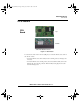
3StackQS_WinCE.book Page 20 Friday, November 21, 2008 11:46 AM Build the Platform Build a Development Platform: Assemble Three Boards Connect Development Platform to PC; Run Preloaded Image 2 Set Bootstrap switches (SW5–SW10) to NAND boot 5 S4 J2 Regulated +5V DC Supply 3 DC power 4 Female RS-232 cable Configure serial console application. 6 COM port 1 Set SW4 Figure 3.4 Connecting the Platform to your PC To connect the 3-Stack platform to your host PC: 1.
3StackQS_WinCE.book Page 21 Friday, November 21, 2008 11:46 AM Build the Platform Build a Demo Platform: Assemble Two Boards 3. Connect the regulated 5V power supply to the appropriate power adapter. Plug the power adapter into an electrical outlet and the 5V line connector into the J2 (5V POWER JACK) connector on the Debug board. See Figure 3-5. 4. Start a serial console application on your host PC with the following configuration Table 3.
3StackQS_WinCE.book Page 22 Friday, November 21, 2008 11:46 AM Build the Platform Build a Demo Platform: Assemble Two Boards CPU Board Personality Board Personality Board 1 Flip over Personality/ 2 Align boards Personality Board CPU Board 3 Install CPU board onto underside of Personality board CPU Board Personality/CPU Assembly Personality Board Figure 3.5 Install CPU Board onto Personality Board i.MX27 PDK 1.0 Quick Start Guide, Rev. 1.
3StackQS_WinCE.book Page 23 Friday, November 21, 2008 11:46 AM Build the Platform Build a Demo Platform: Assemble Two Boards Connect Power Supply; Run Preloaded Demo CPU/Personality Board Regulated +5V DC Supply 1 DC power J12 power jack is on the underside of the Personality board 2 Figure 3.6 Connect Personality Board to Power Supply 1. Connect the regulated 5V power supply to the appropriate power adapter. Plug the 5V line into the J12 (5V POWER JACK) connector on the Personality board.
3StackQS_WinCE.book Page 24 Friday, November 21, 2008 11:46 AM Build the Platform Build a Demo Platform: Assemble Two Boards i.MX27 PDK 1.0 Quick Start Guide, Rev. 1.
3StackQS_WinCE.book Page 25 Friday, November 21, 2008 11:46 AM 4 Using the Demo Image This chapter explains how to use the touch panel and stylus to load the multimedia content to the 3-Stack board, using the provided demo image. Touch Pad Calibration Tool After you have assembled the 3-Stack board and powered it up, the Windows Embedded CE 6.0 image that was loaded to the board will boot up.
3StackQS_WinCE.book Page 26 Friday, November 21, 2008 11:46 AM Using the Demo Image Touch Pad Calibration Tool To calibrate the Touch Panel, follow these steps: 1. Using the stylus pen, click on the cross. The cross will move to the four corners of the screen. If the calibration error is too large, the program will reset and the process will have to be repeated. When the touch panel calibration is successful, the following message is displayed: 2. Tap with the stylus pen in any part of the screen.
3StackQS_WinCE.book Page 27 Friday, November 21, 2008 11:46 AM Using the Demo Image Downloading Multimedia to the 3-Stack Board Downloading Multimedia to the 3-Stack Board There are three ways to load multimedia content to the 3-Stack board using the Windows Embedded CE 6.0 image provided: • Using Active Sync • Using an SD Card • Using a USB Card Using Active Sync Active Sync is a very useful tool to use with a Windows Embedded CE 6.0 device.
3StackQS_WinCE.book Page 28 Friday, November 21, 2008 11:46 AM Using the Demo Image Downloading Multimedia to the 3-Stack Board Figure 4.3 Setting up a Partnership 4. Select Yes, and then click Next. i.MX27 PDK 1.0 Quick Start Guide, Rev. 1.
3StackQS_WinCE.book Page 29 Friday, November 21, 2008 11:46 AM Using the Demo Image Downloading Multimedia to the 3-Stack Board The Select Synchronization Settings options are displayed (Figure 4.4). Figure 4.4 Selecting Synchronization Settings Active Sync establishes communications with the 3-Stack board, and the Active Sync screen displays the connection status (Figure 4.5). Figure 4.5 Viewing the Connection Status i.MX27 PDK 1.0 Quick Start Guide, Rev. 1.
3StackQS_WinCE.book Page 30 Friday, November 21, 2008 11:46 AM Using the Demo Image Downloading Multimedia to the 3-Stack Board 5. To browse the Mobile Device (3-Stack) folders, click on the Explore icon of the Active Sync window A new Windows Explorer window for your Mobile Device opens on the Host PC (Figure 4.6). Figure 4.6 Windows Explorer for Mobile Device 6. To download a multimedia file, drag the file to the Mobile Device window.
3StackQS_WinCE.book Page 31 Friday, November 21, 2008 11:46 AM Using the Demo Image Downloading Multimedia to the 3-Stack Board 9. To access the files, double-click on the "My Device" icon in the Windows Embedded CE 6.0 desktop (on the 3-Stack board). A Windows Explorer window will open, displaying the content you downloaded with Active Sync (Figure 4.7). Figure 4.7 Downloaded Content 10. Plug the headphones to the J19 Audio/Video jack connector in the Personality board. 11.
3StackQS_WinCE.book Page 32 Friday, November 21, 2008 11:46 AM Using the Demo Image Downloading Multimedia to the 3-Stack Board Using an SD Card If you have an SD Card with pictures or other multimedia content, you can use the 3-Stack Board to view its content. To use access the SD Card, follow these steps: 1. Make sure the 3-Stack is powered and running the Windows Embedded CE 6.0 demo image. 2.
3StackQS_WinCE.book Page 33 Friday, November 21, 2008 11:46 AM Using the Demo Image Running the Demo Applications Using a USB Memory Stick You must have a USB mini AB-to-A female connector, for connecting the USB memory stick to the 3-Stack board. To use the USB memory stick with the 3-Stack board, follow these steps: 1. Make sure the 3-Stack is powered and running the Windows Embedded CE 6.0 demo image. 2.
3StackQS_WinCE.book Page 34 Friday, November 21, 2008 11:46 AM Using the Demo Image Running the Demo Applications Running the TV-Out Application The TV Out application has two output formats: PAL and NTSC. You will need a special cable. To use the TV-Out application, follow these steps: 1. Plug the RCA Video/Audio cable jack to the J19 Video/Audio jack on the Personality board. 2. Connect the RCA end to the TV. 3.
3StackQS_WinCE.book Page 35 Friday, November 21, 2008 11:46 AM Using the Demo Image Running the Demo Applications The Properties menu option is displayed ( Figure 4.10). F Figure 4.10 Properties Menu Option i.MX27 PDK 1.0 Quick Start Guide, Rev. 1.
3StackQS_WinCE.book Page 36 Friday, November 21, 2008 11:46 AM Using the Demo Image Running the Demo Applications 4. Select the Backlight tab, clear the two options on the tab, and then click OK at the top right corner of the window (Figure 4.11). Figure 4.11 Selecting the Background Tab i.MX27 PDK 1.0 Quick Start Guide, Rev. 1.
3StackQS_WinCE.book Page 37 Friday, November 21, 2008 11:46 AM Using the Demo Image Running the Demo Applications 5. The power settings on the Control Panel must be modified. To access the Control Panel window, click the Windows logo at the lower left corner and go to Settings Control Panel (Figure 4.12). Figure 4.12 Selecting the Control Panel i.MX27 PDK 1.0 Quick Start Guide, Rev. 1.
3StackQS_WinCE.book Page 38 Friday, November 21, 2008 11:46 AM Using the Demo Image Running the Demo Applications 6. Double-click the Power icon (Figure 4.13). Figure 4.13 Selecting the Power Settings Icon i.MX27 PDK 1.0 Quick Start Guide, Rev. 1.
3StackQS_WinCE.book Page 39 Friday, November 21, 2008 11:46 AM Using the Demo Image Running the Demo Applications 7. Select the Schemes tab (Figure 4.14). Figure 4.14 Selecting the Schemes Tab 8. Change all the drop-down menu options to Never. 9. Click OK. i.MX27 PDK 1.0 Quick Start Guide, Rev. 1.
3StackQS_WinCE.book Page 40 Friday, November 21, 2008 11:46 AM Using the Demo Image Running the Demo Applications 10. Now that the Power saving options are disabled, you may use the TV-Out program without a problem. To run the program, click on the Windows logo at the lower left corner of the display, and then click Run (Figure 4.15). The Run field is displayed. Figure 4.15 Selecting Run i.MX27 PDK 1.0 Quick Start Guide, Rev. 1.
3StackQS_WinCE.book Page 41 Friday, November 21, 2008 11:46 AM Using the Demo Image Running the Demo Applications 11. Type "DisplaySwitcher 0" for TVs using PAL format or "DisplaySwitcher 1" for TVs using NTSC format, and then click OK. Figure 4.16 shows an example for a NTSC TV. Once the program runs, the image should appear at the TV. Figure 4.16 Example of an NTSC TV Usage 12.
3StackQS_WinCE.book Page 42 Friday, November 21, 2008 11:46 AM Using the Demo Image Running the Demo Applications Changing the Windows Embedded CE 6.0 Demo Image Version The PDK system provides one demo image for Windows Embedded CE 6.0. To obtain instructions for switching images and running the selected version of the Windows Embedded CE 6.0 Demo Image on the PDK system, see your Windows Embedded CE 6.0 package, Chapter 5, Preparing for Download and Debugging. i.MX27 PDK 1.0 Quick Start Guide, Rev. 1.
3StackQS_WinCE.book Page 43 Friday, November 21, 2008 11:46 AM Using the Demo Image Ready to Begin Your Development? Ready to Begin Your Development? If you are ready to develop new applications using the i.MX27 PDK, use the following documents to locate the information required for your development: • i.MX27 PDK 1.0 Hardware User's Guide provides all of the hardware information for the 3-Stack board, including the connectors, switches, options, and pins. • i.MX27 PDK 1.0 Windows Embedded CE 6.
3StackQS_WinCE.book Page 44 Friday, November 21, 2008 11:46 AM i.MX27 PDK 1.0 Quick Start Guide PN 926-78297 Rev.