
User's Manual


Implementation
Variable Speed DC Fan Control using the MC9RS08KA2, Rev. 0
20 Freescale Semiconductor
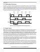
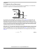
As described in the previous section the overall dead-time duration should be deterministic, the double
WAIT statements in the subroutine can ensure the execution time to be mostly constant. When the MCU
is woken up from the first WAIT (which is normally triggered by the comparator), the timer counter value
is captured and the MCU is then returned to WAIT mode until the timer is overflowed. The subroutine
execution time would be equivalent to the timer overflow period (~128µs) plus some software overhead.
3.4.1 Temperature Conversion
In general, the channel resistance of the temperature sensor reduces as the temperature increases. The
corresponding channel resistance against temperature can usually be retrieved from the sensor data
sheet. For this application the operating temperature range is defined from 25°C to 100°C. When the
ambient temperature is 100°C or above the motor is at maximum speed. The speed drops as the
temperature decreases in 5°C steps. Given the sensor channel resistance values the voltage across the
sensor can be calculated. The corresponding motor speed for a specific temperature range are also
defined and shown in Table 3-3.
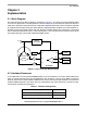
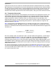
EQ 3-2 shows how the target PWM period value is calculated. The target value is compared with the
measured PWM period every 180 degrees of rotation. The ADC readout delay is considered as constant,
therefore, it is omitted from the motor speed measurement and should be deducted from the target period
calculation, too.
(EQ 3-2)
The timer resolution used in the application is 64µs, the ADC readout time contributes a constant delay
to the overall PWM period, which is ~128µs in this application. The target PWM period used for motor
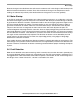
speed control is shown in Table 3-3. The table is stored in the upper memory (FLASH). In RS08
architecture upper memory access is done through the paging window (address $00C0 to $00FF) where
the PAGESEL register is defining the page to be accessed. Simple table lookup method which uses the
captured timer value from the temperature sensor readout as an index in the paging window for the target
PWM period conversion.
For software implementation, the target motor speed must be deduced in terms of timer counts, where it
is used as the target PWM period per commutation. By using Table 3-2 and Table 3-3, a look-up table
can be constructed where the ADC readout value is used as an index to retrieve the target PWM period
for a specific temperature range.
TetPWMPeriodarg
60 RPM⁄
4
---------------------- A D C D e l a y–
TimerResolution
----------------------------------------------------------=