
User's Manual


PC Control Mode
LED Lighting Control using the MC9S08AW60, Rev. 1
Freescale Semiconductor 25
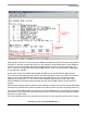
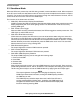
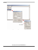
Figure 3-3. User Interface Menu
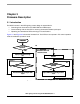
When the MCU receives a control command or PWM input data from the PC, the firmware interprets the
information to take the corresponding actions. It may update the output PWM values in next PWM duty
or delivery of the corresponding LED control parameter back to the PC. Three timer channels in the
timer 1 module are configured to edge-aligned PWM operation mode. This generates the PWM signals
for the RGB color channels.
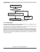
By the proper control of the RGB channel PWM, the LED box can provide different lighting effects.
If you select the white balance mode to AUTO, the LED output gives a white color output. The firmware
retains control of the RGB PWM ratio based on the preset white color. You can adjust the output
brightness by pressing the + or − key in the host PC keyboard. Alternatively, you can input a green
channel PWM value and the firmware calculates the blue and red PWM values to give the resultant
intensity.
A demonstration display feature is available. After enabling this feature, the firmware adjusts RGB PWM
so the light box switches among different preset colors, delivery fade in and fade out lighting effects, etc.
You can also set the PWM to different frequencies. At a lower PWM frequency, such as 30 Hz, the flicking
phenomenon is more noticeable. This phenomenon can be minimized or removed by setting the PWM
frequency to a higher value.
There are examples at the end of this section showing how to control the LED box through the host PC.