
User's Manual


Firmware Description
LED Lighting Control using the MC9S08AW60, Rev. 1
24 Freescale Semiconductor
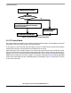
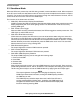
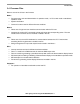
Figure 3-2. Firmware Flow: PWM Adjustment
3.2 PC Control Mode
Every time the MCU is powered up, the firmware detects the status of SW1. The LED lighting control box
is operated in PC control mode if SW1 is not being pressed.
In this mode, you control the LED output through the host PC. The MCU uses the serial communication
interface (SCI) module to communicate to the COM port of the host PC.
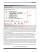
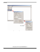
After entering this mode, the MCU sends out a number of string characters to the PC COM port. These
strings are the contents of the user interface menu displayed in the PC screen. This user interface menu
guides you on how to control the LED box by different function keys. The MCU also sends out existing
PWM control parameters to the host for display. For examples, parameters such as existing RGB PWM
output values, white balance mode, and PWM frequency are displayed. Figure 3-3 shows the PC screen
for the user control menu.
Prompt for green channel PWM input and calculate the
two remaining channels’ PWM values according to
existing color temperature
Adjust PWM width in next PWM cycle
PWM value input to one channel
Yes
Get the other two channel
values from user input
Auto White balance?
No
Prompt for green channel PWM input and calculate the
two remaining channels’ PWM values according to
existing color temperature
Adjust PWM width in next PWM cycle
Adjust PWM width in next PWM cycle
PWM value input to one channelPWM value input to one channel
Yes
Get the other two channel
values from user input
Get the other two channel
values from user input
Auto White balance?Auto White balance?
No