
User's Manual


LED Lighting Control using the MC9S08AW60, Rev. 1
Freescale Semiconductor 23
Chapter 3
Firmware Description
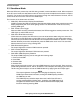
3.1 Introduction
The MCU firmware in this LED lighting control design is responsible for:
• Controlling timer channels for the RGB LED color PWM output
• Communicating with the host PC for receiving command and data input/output
• Operating as a standalone LED box through on board buttons
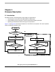
Figure 3-1 and Figure 3-2 shows the firmware flow. The LED box can operate in PC control operation
mode or standalone operation mode.
Figure 3-1. Firmware Flow: Main Program
Display control menu through
SCI
Yes
No
Initialization
PC Control Mode
Operation?
Enable I/O for PCB button
detection
Yes
No
Valid command from PC?
Process commands and adjust PWM
output
Yes
No
Any PCB button
pressed?
Adjust PWM output according to button
event
*Standalone demo box
without PC control
Display control menu through
SCI
YesYes
No
InitializationInitialization
PC Control Mode
Operation?
Enable I/O for PCB button
detection
YesYes
No
Valid command from PC? Valid command from PC?
Process commands and adjust PWM
output
YesYes
No
Any PCB button
pressed?
Any PCB button
pressed?
Adjust PWM output according to button
event
*Standalone demo box
without PC control