
User's Manual


LED Driver Design Procedures
LED Lighting Control using the MC9S08AW60, Rev. 1
Freescale Semiconductor 19
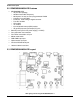
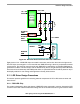
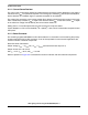
Figure 2-3. DC-to-DC Boost Converter and Linear LED Driver
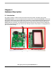
Eight pieces of 3-in-1 RGB LED chips connected in series are used to form the multi-color light source.
The LED chips are arranged in 2 x 4 format and each RGB LED string is driven by a separated constant
current source. The average current through each RGB LED is controlled by an individual PWM signal
generated from MCU. The final output color is determined by the mix of light emitted by RGB LEDs that
are almost in linear relationship with PWM pulse width. An optical diffuser film should be placed on top of
the display window for color mixing and brightness uniformity enhancement.
2.11 LED Driver Design Procedures
This section presents guidelines for selecting external components for DC-to-DC boost converter and
linear drivers.
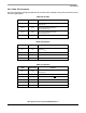
2.11.1 RGB LED Chip
The system is designed to drive eight pieces of RGB LED chips connected in a series. Assume the LED
current for each color is 50mA and forward voltage is 2.3V for red LED and 3.3V for green and blue LEDs.
Vout = 30V
DC-to-DC
Boost
Converter
(MC34063)
V
REF
8 LEDs
Rs
Driver R
Driver G
Driver B
8 LEDs
8 LEDs
V
LED
x 8
V
DROP
V
RS
I
LED
= 50mA
Vin = 12V
R-Channel
PWM
G-Channel
PWM
B-Channel
PWM
Vout = 30V
DC-to-DC
Boost
Converter
(MC34063)
V
REF
8 LEDs
Rs
Driver R
Driver G
Driver B
8 LEDs
8 LEDs
V
LED
x 8
V
DROP
V
RS
I
LED
= 50mA
Vin = 12V
R-Channel
PWM
G-Channel
PWM
B-Channel
PWM