
User's Manual


Hardware Description
LED Lighting Control using the MC9S08AW60, Rev. 1
18 Freescale Semiconductor
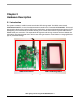
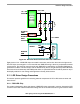
2.10 LED Driving Board
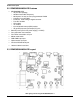
In general, LEDs have a nonlinear I-V behavior and current limitation is required to prevent the power
dissipation to exceed a maximum limit. Therefore, the ideal source for LED driving is a constant current
source. A linear type LED driver is used in this reference design and the block diagram is shown in
Figure 2-4. The major advantage of linear driver is fast turn ON and OFF response times to support high
frequency PWM dimming method and wide range control on dimming level. An integrated DC-to-DC
boost converter (MC34063) generates the high voltage required for LED driving in series and is shared
with RGB channels, but the drawback is the power loss on R channel is higher than G or B channels.
Individual DC-to-DC block should be used for each channel in power sensitive applications.
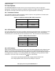
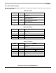
Pin 7 DCDC_CTL1 Connected to MCU PTF4/TPM2CH0
Pin 8 DCDC_CTL2 Connected to MCU PTF5/TPM2CH1
Pin 9 DCDC_CTL3 Connected to MCU PTE3/TPM1CH1
Pin 10 GND —
Table 2-13. User Assignable Input (Continued)
CON13 Signal Name Remarks