
User's Manual
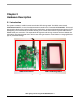


User Options
LED Lighting Control using the MC9S08AW60, Rev. 1
Freescale Semiconductor 17
NOTE
Connectors Type A and H share the same connection, so either one of the
sensor interfaces can be used for sensor input.
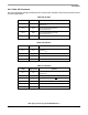
Table 2-11. Sensor Interface Type H
CON11 Signal Name Remarks
Pin 1 3V Sensor reference voltage
Pin 2 5V Sensor supply voltage
Pin 3 GND —
Pin 4 NC —
Pin 5 SEN_IN_G
Sensor input (Green), Connected to MCU
PTB1/ADP1 through operational amplifier U5A
Pin 6 SEN_IN_R
Sensor input (Red), Connected to MCU
PTB0/ADP0 through operational amplifier U5D
Pin 7 SEN_IN_B
Sensor input (Blue), Connected to MCU
PTB2/ADP2 through operational amplifier U5B
Pin 8 NC —
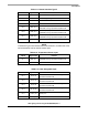
Table 2-12. Temperature Sensor Input
CON12 Signal Name Remarks
Pin 1 SEN_IN_T
10 kΩ pullup to V
DD
, Connected to MCU
PTB3/ADP3 through operational amplifier U5C
Pin 2 GND —
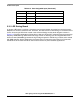
Table 2-13. User Assignable Input
CON13 Signal Name Remarks
Pin 1 FB_IN_R
Connected to MCU PTD0/ADP8 through
operational amplifier U6D
Pin 2 FB_IN_G
Connected to MCU PTD1/ADP9 through
operational amplifier U6A
Pin 3 FB_IN_B
Connected to MCU PTD2/ADP10 through
operational amplifier U6B
Pin 4 FB_IN_PW
Connected to MCU PTD3/ADP11 through
operational amplifier U6C
Pin 5 DCDC_EN
Connected to MCU PTC3/TXD2 and connector
CON3 pin 8
Pin 6 DCDC_ER Connected to MCU PTC5/RXD2