
User's Manual
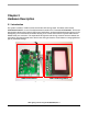


Hardware Description
LED Lighting Control using the MC9S08AW60, Rev. 1
16 Freescale Semiconductor
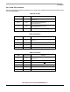
Table 2-8. PWM Port
CON4 Signal Name Remarks
Pin 1 PWM R Connected to MCU PTF0/TPM1CH2
Pin 2 PWM G Connected to MCU PTF1/TPM1CH3
Pin 3 PWM B Connected to MCU PTE2/TPM1CH0
Pin 4 GND —
Table 2-9. LED Light Box Interface
CON3 Signal Name Remarks
Pin 1 & 2 12V 12V power for LED light box
Pin 3 & 4 GND —
Pin 5 PWM R Connected to MCU PTF0/TPM1CH2
Pin 6 PWM G Connected to MCU PTF1/TPM1CH3
Pin 7 PWM B Connected to MCU PTE2/TPM1CH0
Pin 8 DCDC_EN
Connected to MCU PTC3/TXD2
Reserved pin for DC to DC converter ON/OFF
control
Pin 9 & 10 NC —
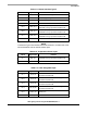
Table 2-10. Sensor Interface Type A
CON10 Signal Name Remarks
Pin 1 5V Sensor supply voltage
Pin 2 GND —
Pin 3 SEN_IN_B
Sensor input (Blue), Connected to MCU
PTB2/ADP2 through operational amplifier U5B
Pin 4 SEN_IN_G
Sensor input (Green), Connected to MCU
PTB1/ADP1 through operational amplifier U5A
Pin 5 SEN_IN_R
Sensor input (Red), Connected to MCU
PTB0/ADP0 through operational amplifier U5D
Pin 6 NC —