
User's Manual


Hardware Description
LED Lighting Control using the MC9S08AW60, Rev. 1
14 Freescale Semiconductor
2.9 User Options
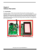
The DEMO9S08AW60LED includes various input and output devices to assist in application
development. These devices include four pushbutton switches, four LEDs, and an operational amplifier
with RC filter connected at each ADC input channel for signal amplification and filtering.
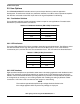
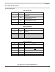
2.9.1 Pushbutton Switches
Four pushbutton switches provide momentary active low input for user applications. The table below
describes the pushbutton switch connections.
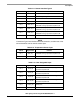
2.9.2 LED Indicators
Four green LED indicators (D1-D4) are provided to assist during code development. The LEDs are active
low and illuminated when a logic low signal is driven from the MCU port pin. Two of the LEDs are
connected to port A, and the other two are connected to Port C. The connections are described below:
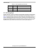
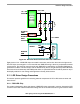
2.9.3 ADC Interface
Eight operational amplifiers are provided to assist users in developing applications with feedback control
signals. For examples, the signal generated by an optical sensor in LED backlight system should be
scaled to a level matched with the ADC input range without any saturation. Each operational amplifier can
be configured as an inverting or non-inverting amplifier with variable gain setting by different resistor
connections. A RC filter is also connected at each output for noise filtering.
NOTE
The maximum operational amplifier output voltage should be limited to the
V
DD
voltage applied to MCU to prevent any damage on input port.
Table 2-3. Pushbutton Switches (SW1-SW4) Connections
Switch MCU Port
SW1 PTG0/KBI0
SW2 PTG1/KBI1
SW3 PTG2/KBI2
SW4 PTG3/KBI3
Table 2-4. LEDs (D1-D4) Connections
LED MCU Port
D1 PTA0
D2 PTA1
D3 PTC2
D4 PTC4