
User's Manual


Development Support
LED Lighting Control using the MC9S08AW60, Rev. 1
Freescale Semiconductor 13
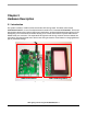
2.4 Development Support
Application development and debug for the MC9S08AW60 is supported through a 6-pin BDM header
(CON8). The pinout is as follows:
2.5 Power
The DEMO9S08AW60LED is powered externally through the barrel connector CON2. This connector is
a 2.5 mm, center positive connector. Voltage supplied through this connector should be positive 12 volts
DC. This is also the supply voltage for the LED light box.
The DEMO9S08AW60LED can be run with V
DD
set to 5 or 3 volts. To run the board at 3V, move jumper
JP1 to the 1-2, 3V position.
LED D5 turns green to let you know that power has been correctly applied to the board.
2.6 Reset Switch
The reset switch (SW5) provides a way to apply a reset to the MCU. The reset switch is connected directly
to the RESET
signal of the MCU. A 10 kΩ pullup resistor to V
DD
on the RESET signal allows for normal
operation. When the reset switch is pressed, the RESET signal is grounded and the MCU recognizes a
reset.
2.7 Clock Source
An on-board 16 MHz crystal (X1) is connected between the XTAL and EXTAL pins of the MCU. This offers
flexibility on clock source selection. Refer to the MC9S08AW60 data sheet for details on how to use the
internal clock generation (ICG) module to generate the system clocks for the MCU.
2.8 RS-232
An RS-232 translator provides RS-232 communication on COM connector P2. This connector is a 9-pin
Dsub right angle connector. TXD and RXD signals are routed from the MCU to the RS-232 transceiver.
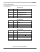
Table 2-1. BDM Connector (CON8) Pinout
BKGD 1 2 GND
NC 3 4 RESET
NC 5 6 V
DD
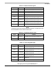
Table 2-2 . RS-232 Connections
MCU Port COM Signal I/O Port Connector
PTE0/TXD1 TXD OUT P2-2
PTE1/RXD1 RXD IN P2-3