
Stereo System - Digital Audio Signal Processor User Manual

Serial Host Interface Programming Model
DSP56364 24-Bit Digital Signal Processor Users Manual, Rev. 2
Freescale Semiconductor 7-5
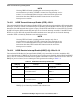
The interrupt vector table for the Serial Host Interface is shown in Table 7-1 and the exceptions generated
by the SHI are prioritized as shown in Table 7-2.
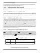
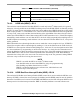
7.4.1 SHI Input/Output Shift Register (IOSR)—Host Side
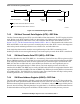
The variable length Input/Output Shift Register (IOSR) can be viewed as a serial-to-parallel and
parallel-to-serial buffer in the SHI. The IOSR is involved with every data transfer in both directions (read
and write). In compliance with the I
2
C and SPI bus protocols, data is shifted in and out MSB first. In
single-byte data transfer modes, the most significant byte of the IOSR is used as the shift register. In 16-bit
data transfer modes, the two most significant bytes become the shift register. In 24-bit transfer modes, the
shift register uses all three bytes of the IOSR (see Figure 7-5).
NOTE
The IOSR cannot be accessed directly either by the host processor or by the
DSP. It is fully controlled by the SHI controller logic.
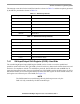
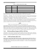
Table 7-1 SHI Interrupt Vectors
Program Address Interrupt Source
VBA:$40 SHI Transmit Data
VBA:$42 SHI Transmit Underrun Error
VBA:$44 SHI Receive FIFO Not Empty
VBA:$48 SHI Receive FIFO Full
VBA:$4A SHI Receive Overrun Error
VBA:$4C SHI Bus Error
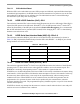
Table 7-2 SHI Internal Interrupt Priorities
Priority Interrupt
Highest SHI Bus Error
SHI Receive Overrun Error
SHI Transmit Underrun Error
SHI Receive FIFO Full
SHI Transmit Data
Lowest SHI Receive FIFO Not Empty