Freescale Semiconductor User’s Guide DEMO9S08AC60EUG Rev. 0.1, 11/2007 DEMO9S08AC60E User’s Guide © Freescale Semiconductor, Inc., 2007. All rights reserved.
How to Reach Us: Information in this document is provided solely to enable system and software implementers to use Freescale Semiconductor products. There are no express or implied copyright licenses granted hereunder to design or USA/Europe/Locations not listed: Freescale Semiconductor Literature Distribution P.O. Box 5405, Denver, Colorado 80217 1-800-521-6274 or 480-768-2130 fabricate any integrated circuits or integrated circuits based on the information in this document.
User’s Guide — DEMO9S08AC60E Table of Contents Section 1. 1.1 Introduction. . . . . . . . . . . . . . . . . . . . . . . . . . . . . . . . . . . . . . . . . . . . . . 9 1.2 System Requirements . . . . . . . . . . . . . . . . . . . . . . . . . . . . . . . . . . . . . . 9 1.3 DEMO9S08AC60E Layout . . . . . . . . . . . . . . . . . . . . . . . . . . . . . . . . 10 1.4 Features . . . . . . . . . . . . . . . . . . . . . . . . . . . . . . . . . . . . . . . . . . . . . . . . 11 1.5 References. . . . . . .
1.13.6 1.13.7 Potentiometer . . . . . . . . . . . . . . . . . . . . . . . . . . . . . . . . . . . . . . . . . 20 I/O Connector. . . . . . . . . . . . . . . . . . . . . . . . . . . . . . . . . . . . . . . . . 20 DEMO9S08AC60E User’s Guide, Rev. 0.
User’s Guide — DEMO9S08AC60E List of Figures 1-1 DEMO9S08AC60E Top Side . . . . . . . . . . . . . . . . . . . . . . . . . . . . . . . 10 DEMO9S08AC60E User’s Guide, Rev. 0.
DEMO9S08AC60E User’s Guide, Rev. 0.
User’s Guide — DEMO9S08AC60E List of Tables 1-1 1-2 1-3 1-4 1-5 1-6 1-7 1-8 1-9 1-10 1-11 1-12 MC9S08AC60 Memory Map . . . . . . . . . . . . . . . . . . . . . . . . . . . . . . 12 BDM Connector (J32) Pinout . . . . . . . . . . . . . . . . . . . . . . . . . . . . . . 13 Jumper Settings in USB Power Mode . . . . . . . . . . . . . . . . . . . . . . . . 14 Jumper Settings in EXT Power Mode . . . . . . . . . . . . . . . . . . . . . . . . 15 Jumper Settings in I/O Connector Power Mode . . . . . . . . . . . . .
DEMO9S08AC60E User’s Guide, Rev. 0.
User’s Guide — DEMO9S08AC60E Section 1. 1.1 Introduction The DEMO9S08AC60E is a demonstration board for the Freescale MC9S08AC60. Through the on-board BDM port, the DEMO9S08AC60E allows users to develop code and evaluate the MC9S08AC60 processor. To set up and run the included demo program, please refer to the Quick Start guide supplied with the DEMO9S08AC60E. There is also a soft copy of the quick start guide on the included resource CD. 1.
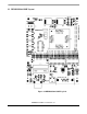
1.3 DEMO9S08AC60E Layout Figure 1-1DEMO9S08AC60E Top Side DEMO9S08AC60E User’s Guide, Rev. 0.
1.
1.5 References The following reference documents are included on the enclosed documentation CD: • DEMO9S08AC60E_QS.pdf -- Quick Start Guide • SPF-20805.pdf -- Schematic • DEMO9S08AC60E_UG.pdf -- User’s Guide (this document) 1.6 Getting Started To get started quickly, please refer to the DEMO9S08AC60E Quick Start Guide. This guide will walk you through connecting your DEMO9S08AC60E to your PC, running a test program, and installing CodeWarrior Development Studio. 1.
1.8.1 Integrated BDM The DEMO9S08AC60E features an integrated USB-BDM debugger from P&E Microcomputer Systems. All necessary signals are provided via the integrated debugger. A USB type B connector (J33) provides the connection between the DEMO9S08AC60E and your host PC. The integrated debugger provides the DEMO9S08AC60E with power eliminating the need to power the board externally. Power is derived from the USB bus, therefore total current consumption should not exceed 500mA.
1.9 Power The DEMO9S08AC60E allows the user to power the board in several different ways. 1.9.1 USB-BDM Interface The default power option is to power the board through the integrated USB-BDM interface. To power the board in this manner, simply connect the supplied USB cable from the USB connector on the DEMO9S08AC60E (J33) to a USB port on your host computer. LED D1 will light green to let you know that power has been correctly applied to the board.
Table 1-4 Jumper Settings in EXT Power Mode Jumper Default Position W1 2-3 5V Sets the board for 5V operation W2 1-2 EXT Sets the board to be powered externally through J1 P_IO_5V Outputs 5V on pin 1 of the I/O connector, J35. This jumper should be removed if you do not want to output 5V on this pin. W3 1-2 Setting Description 1.9.3 I/O Connector The DEMO9S08AC60E can also be powered through pin 1 of the I/O connector J35.
1.9.4 3 Volt Operation The DEMO9S08AC60E can be run with VDD set to either 5 volts or 3 volts. To run the board at 3V when using any of the three power options, move jumper W1 to the 1-2, 3V position. 1.10 Reset Switch The reset switch (SW6) provides a way to apply a reset to the MCU. The reset switch is connected directly to the RESET_B signal of the MCU. A 10K pull up resistor to VDD on the RESET_B signal allows for normal operation.
Table 1-7 COM Connector (J34) Pinout Pin Signal Name 1 Connected to pins 4 and 6 through zero ohm resistors R55 and R56 2 TXD 3 RXD 4 Connected to pins 1 and 6 through zero ohm resistors R55 and R56 5 GND 6 Connected to pins 1 and 4 through zero ohm resistors R55 and R56 7 NC 8 NC 9 NC 1.13 User Options The DEMO9S08AC60E includes various user input and output devices to assist in application development and silicon evaluation.
switches by removing the appropriate jumper. The table below describes the pushbutton switch connections Table 1-8 Pushbutton Switch (SW1 - SW4) Connections Switch MCU Port Jumper SW1 PTC2 J12 SW2 PTC6 J13 SW3 PTD3 J11 SW4 PTD2 J10 1.13.2 Light Bar A 10 red LED light bar (LED1) is provided to assist users during code development. The LEDs are active low and are illuminated when a logic low signal is driven from the MCU port pin. Eight of the LEDs on the light bar are connected to port F.
1.13.3 Rocker Switches Eight rocker switches (SW5) are provided for user application development. These switches are active low and input a logic low when set to the closed position. There are no external pullups on these switches so the internal pullups should be enabled on the MCU port pins to ensure proper operation. Port A pins can be disconnected from the rocker switches by removing the appropriate jumper.
Table 1-11 Accelerometer (U5) Connections Accelerometer Function MCU Port Jumper Sleep Mode PTC4 J5 Amplified Y Output PTD4 J6 Amplified X Output PTD5 J7 Raw Y Output PTD6 J8 Raw X Output PTD7 J9 1.13.5 Light Sensor A photo detect IC (U4) combines a photodiode and a current amplifier on a single IC to provide variable current. The light sensor is connected to the MCU on PTD1. PTD1 can be disconnected from the light sensor by removing jumper J4. 1.13.
board can pass through the top of the board.
DEMO9S08AC60E User’s Guide, Rev. 0.
How to Reach Us: Information in this document is provided solely to enable system and software implementers to use Freescale Semiconductor products. There are no express or implied copyright licenses granted hereunder to design or USA/Europe/Locations not listed: Freescale Semiconductor Literature Distribution P.O. Box 5405, Denver, Colorado 80217 1-800-521-6274 or 480-768-2130 fabricate any integrated circuits or integrated circuits based on the information in this document.