
user manual


Block Guide — S12EETX4KV0 V00.04
14
Section 3 Memory Map and Registers
3.1 Overview
This section describes the memory map and registers for the EEPROM module.
3.2 Module Memory Map
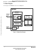
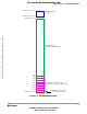
A linear EEPROM memory map is shown in Figure 3-1. The HCS12X architecture actually places the
EEPROM memory addresses between logical addresses $0800 and $1000 with $0800 to $0BFF
representing 1K byte of paged EEPROM memory and $0C00 to $0FFF representing 1K byte of fixed
EEPROM memory. The EPROT register, described in section 3.3.5, can be set to protect the upper region
in the EEPROM memory from accidental program or erase. The EEPROM addresses covered by this
protectable region are shown in the EEPROM memory map. The default protection setting is stored in the
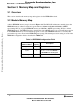
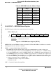
EEPROM configuration field as described in Table 3-1.
Table 3-1 EEPROM Configuration Field
EEPROM Memory
Address Offset
Size
(bytes)
Description
$_FFC
1
Reserved
$_FFD
1
EEPROM Protection byte
Refer to Section 3.3.5 EPROT —
EEPROM Protection Register
$_FFE - $_FFF
2
Reserved
Frees
cale Semiconductor,
I
Freescale Semiconductor, Inc.
For More Information On This Product,
Go to: www.freescale.com
nc...