KVM-08H / KVM-16H Switch with Remote Console Stackable TWO-CONSOLE (One Local , One CAT5 Remote) 8 port / 16 port 19” RACK MOUNTABLE PS/2 KVM SWITCH USER’S MANUAL
freedom9 Inc. - 1 Year Limited Warranty Subject to the terms and conditions set forth herein, freedom9 Inc. ("freedom9") provides this limited warranty ("Limited Warranty"): only to the person or entity that originally purchased ("Customer") the product ("Product") from freedom9 or its authorized reseller or distributor.
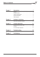
Table of Contents Chapter 1 Introduction . . . . . . . . . . . . . . . . . . . . . . . .1 Features . . . . . . . . . . . . . . . . . . . . . . . . . . . . . . . . . . . . . .2 Package contents . . . . . . . . . . . . . . . . . . . . . . . . . . . . . . .2 Technical specifications . . . . . . . . . . . . . . . . . . . . . . . . . .3 System requirement . . . . . . . . . . . . . . . . . . . . . . . . . . . . .4 Cable diagrams . . . . . . . . . . . . . . . . . . . . . . . . . . . . . . . .
Chapter 1: Introduction Thank you for purchasing the Two-Console PS/2 KVM switch. The Two-Console PS/2 KVM switch can save your MONEY, TIME, SPACE, EQUIPMENT and POWER. The Two-Console switch controls multiple computers from one Keyboard, Mouse and VGA Monitor with complete keyboard and mouse emulation for simultaneous computer boot-up. It has various features such as one local console port and one remote console up to 500-feet away using a CAT5 console port.
Chapter 1: Introduction Features • 8/16 port Two-Console PS/2 KVM switch is standard 1U 19” rack mount size design. • Support one local console and one CAT5 remote console up to 500 feet away from KVM switch. • Support Microsoft® Intellimouse®, Microsoft® Intellimouse® Explorer, Logitech Net Mouse or the other fully compatible MS mice. • Support DOS, Win3.X, Win95/98/98SE/2000/ME/XP, WinNT, Netware, Unix, Linux. • Support iMAC, Power MAC and Sun Microsystems with USB port (USB-PS/2 adapter required).
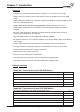
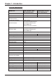
Chapter 1: Introduction Technical Specifications Model No.
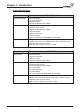
Chapter 1: Introduction System Requirements Model No.
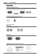
Chapter 1: Introduction Cable Diagrams Computer Port Special Cable: 1 to 3 Hi Density KVM cable (KCB-1236F or KCB-1231) HDDB 15 pin male to one HDDB 15 pin video and Mini Din 6 pin keyboard and mouse connectors AT to PS/2 keyboard adapter: (Optional) Din 5 pin Male to Mini Din 6 pin Female Daisy Chain Cable: PS/2 Cable: Din 5 pin Male to Mini Din 6 pin Female VGA Cable: HDDB15 pin Male to Male CAT5/5E/6 Straight Through UTP/STP Cable: 4P8C 5
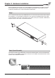
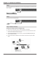
Chapter 2: Hardware Installation Before installation, please make sure all the peripherals and computers have been turned off. The installation below is based on 8 port-Rack Mount KVM Switch. Please follow the same installation procedure for the 16 port Rack Mount KVM Switch. Step 1 Find a convenient place to put your KVM Switch. Its 19” rack mount form factor makes it ideal to be mounted on a 19” rack. When mounting to a rack, attach the included brackets to the sides of the KVM Switch.
Chapter 2: Hardware Installation Step 3 Connect the keyboard to the KVM Switch. If you have an AT type keyboard, you will need an AT to PS/2 adapter. Step 4 Connect the mouse to the KVM Switch. Step 4-1 (Remote Console) Extending your computer console up to 500 feet away: (1) Make sure the CAT5 cable used is a straight through type. (see page 5) (2) Plug one end of the CAT5 cable into the RJ-45 connector of the PS/2 KVM switch and the other end into KVM CAT5 receiver RJ-45 port.
Chapter 2: Hardware Installation NOTE: 1. Local console and Remote console of KVM Switch will have the same priority to control computer, just like a computer connected to two consoles. The remote console can control both the local computer and remote computer connected to KVM switch; however, the local console can only control the computers on local side. There will be a conflict, if the local console and remote console access the computer simultaneously.
Chapter 2: Hardware Installation Step 7 Check all of the connections carefully. The keyboard and mouse connectors are color coded to help in connecting the keyboard and mouse cables to the correct ports. Step 8 Attach the power supply to the KVM unit and plug the other end into an electrical receptacle. Now you will see the LED for Port 1 light up, and you will hear a beep. Switch on your monitor.
Chapter 2: Hardware Installation Daisy Chain Connection Diagram Please use the 3 ft (91.44cm), 3 to 3 daisy chain Cable to daisy chain the KVM Switch. A. Connect Keyboard, Mouse and Monitor to the console port (white color block) of bank 1 KVM switch. B. Use one end of 3 to 3 Cable to connect the daisy chain port of bank 1 and the other end to the console port (white color block) of bank 2 KVM switch. C. Please repeat item B to daisy chain more bank as you want.
Chapter 3: Console Operation Password Protection There is an administration password for locking the console display and switching between managed computers. This password can be set by using the OSD. The password supports up to 8 digits, and only accepts “ A~Z ” , “ 0~9 ” . The default password is “ 00000000 ” . For security reasons, please change the default password the first time you configure the KVM switch. It is strongly recommend to write down the new password.
Chapter 3: Console Operation Selecting Computer Using Hot Key You can conveniently command your KVM SWITCH by keyboard hot key entry. To send commands to the KVM SWITCH, the “SCROLL LOCK” key must be pressed twice within 2 seconds, then you will hear a confirmation beep that the keyboard is in hot key mode. If you have not pressed any additional key in hot key mode within 2 seconds, the keyboard will return back to the normal Operation System control state.
Chapter 3: Console Operation Selecting Computer through Hot Key - Example Example: A. To access a computer attached to Port 2 of Bank 3. You can press through hot key as below: Scroll lock + Scroll lock + 3 + 0 + 2 B. To access a computer attached to next Bank, You can press through hot key as below: Scroll lock + Scroll lock + Page Down NOTE: Use numeric keys on the keyboard to select Bank no. and Port no. Numeric keys on the keypad are not available as a hot key command.
Chapter 3: Console Operation Hot Plug Function KVM switch supports “ Hot Plug ” function. When mouse/keyboard connection has been changed from one port to the other, it is not necessary to reboot the managed computer for the change to take effect. NOTE: Some O.S. (Operation Systems) like SCO Unix are unable to support “ Hot Plug ” function. If you apply “Hot Plug” to this kind of O.S., it will cause unpredictable behavior or shut down the computer. Before using “ Hot Plug ” , please make sure your O.S.
Chapter 3: Console Operation OSD OPERATION Details When you access the OSD menu by using the hot keys, you will see the following window pop up on your monitor. The 1st line bar is Bank No. The 2nd block is your KVM’s computer system name list. You will find the system number list from 01 to 08. You can define your system name with a maximum of 8 levels. The factory default of the 8 port KVM (or 16 for KVM-16H) switch is “SYSTEM 01”, “SYSTEM 02”,…, “SYSTEM 08”.
Chapter 3: Console Operation OSD OPERATION Details Sun symbol “ The sun symbol “ status. ” indicates a powered on status for the KVM port. ” beside the computer system name shows that computer is at powered on Use up arrow key “ ” or down arrow key “ ” to select KVM port. Use up arrow key “ ” or down arrow key “ ” to select port for destination computer system name. After selecting the KVM port you want, press the ENTER Key to immediately switch to that KVM port.
Chapter 3: Console Operation OSD OPERATION Details continued 1. The “OSD: 10 SEC” means that the OSD windows display or computer system name will display for 10 sec. on your monitor. You can modify it from 05 sec to 99 sec. The factory default value is 10 sec. 2. “SCAN ” is the scan interval between one KVM port hopped to the next KVM port. The default SCAN time is 10 sec and the maximum scan time is 99 sec. 3.
Chapter 4: Troubleshooting 1. Make sure that all cables are well connected. Label all of cables with the number for each computer respectively to avoid confusion. 2. To avoid ghosting and degradation, the recommended VGA cable distance is 5 meters (16.4 feet) maximum. Normally, the cable length is based on driver capacity of your VGA card. If you need a longer VGA cable, please use a VGA extender to accomplish your application. 3. The recommended PS/2 cable distance is 5 meters (16.4 feet) maximum.
Certifications FCC This equipment has been tested and found to comply with Part 15 of the FCC Rules. Operation is subject to the following two conditions: (1) This device may not cause harmful interference (2) This device must accept any interference received. Including interference that may cause undesired operation.
© 2005 freedom9 Inc.