
Installation Sheet

Assembly Instructions
Item No. FR35601
start here
1. Find a clear area in which you can work.
2. Unpack fixture from the carton.
3. Carefully review instructions prior to assembly.
*** The construction of this fixture will be accomplished by first
mounting the mounting strap to the junction box, making all
necessary electrical connections, hanging the fixture from the
ceiling, and then installing the glass.
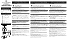
1. Prepare gem strap (A) for mounting by threading two screws (B)
provided into back of gull wing bracket of gem strap (A) – see
Drawing 1.
Be sure the holes into which the screws are threaded match the
spacing of holes (D) in the canopy (G) – see Drawing 1 and 2.
2. Mount gem strap (A) to junction box (J), using the two 1’’ screws
(C).
SAFETY WARNING: READ WIRING AND GROUNDING INSTRUCTIONS
(I.S. 18) AND ANY ADDITIONAL DIRECTIONS. TURN POWER SUPPLY OFF
DURING INSTALLATION. IF NEW WIRING IS REQUIRED, CONSULT A
QUALIFIED ELECTRICIAN OR LOCAL AUTHORITIES FOR CODE
REQUIREMENTS.
1. Hang the fixture by slipping the mounting holes (D) in the
canopy (1) over screws (B), mounted in strap (A) previously – see
Drawing 2.
2. Thread ball knobs (E) onto end of screw (B) and tighten to secure
fixture.
Les Instructions D’assemblage
Item No. FR35601
commencez ici
1. Trouvez un espave libre dans lequel vous pouvez travailler.
2. Déballez appareil de la boîte.
3. Examinez attentivement les instructions avant le montage.
*** La construction de ce dispositif sera réalisé selon la premiére de
montage de la bride de montagede la boîte de jonction, toutes les
connexions électriques nécessaires, accrocher le projecteur á partir du
plafond, puis l’installation du verre.
1. Préparer bracelet de pierres précieuses (A) pour le montage en vissant
deux vis (B) prévu á l’arriére du aile de mouette support de sangle de
gemme (A) – Voir Schéma 1.
Assurez-vous que les trous dans lesquels les vis sont vissées
correspondent á l’espacement des trous (D) dans la canopée (G) – Voir
Schéma 1 et 2.
2. Bracelet bijou de montage (A) á la boîte de jonction (J), á l’aide des
deux vis 25.4 mm (C).
AVERTISSEMENT DE SECURITE: LIRE CABLAGE ET INSTRUCTIONS DE MISE
(IS 18), ET TOUTE AUTRE INSTRUCTION. COUPER L’ALIMENTATION
ELECTRIQUE PENDANT L’ONSTALLATION. SI DE NOUVELLES CABLAGE
N’EST NECESSAIRE, CONSULTEZ UN ELECTRICIEN QUALIFIE OU AUTORITES
LOCALES POUR EXIGENCES DU CODE..
1. Suspendez l’appareil en glissant les trous de fixation (D) la canopée (1)
sur les vis (B), monté en sangle (A) précédemment – Voir Schéma 2.
2. Boutons de boule de la discussion (E) sur l’extrémité de la vis (B) et
serrer pour sécuriser appareil.
Instrucciones de montaje
Item No. FR35601
empezar aquí
1. Busque un lugar claro en el que se puede trabajar.
2. Desembale accesorio de la caja.
3. Revise cuidadosamente las Instrucciones antes del montaje.
*** La construction de este dispositivo se logra mediante el
montaje de la primera correa de montaje a la caja de conexiones,
por lo que todas las conexiones eléctricas necesarias, el aparato de
la que cuelga del techo, y luego la instalación del vidrio.
1. Prepare correa joya (A) para el montaje roscando los dos tornillos
(B), siempre en la parte posterior de ala de gaviota soporte de la
correa joya (A) – Véase la Figura 1.
Asegúrese de que los agujeros en los que se enroscan los tornillos
coincidan con el espaciamiento de los agujeros (D) en el dosel (G)
– Véase la Figura 1 y 2.
2. Correa joya mount (A) a la caja de conexiones (J), con los dos
tornillos 25.4 mm (C).
ADVERTENCIA DE SEGURIDAD: LEA LAS INSTRUCCIONES DE CABLEADO
Y LA TIERRA (IS 18), E INSTRUCCIONES ADICIONALES. APAUGE LA
ALIMENTACIÓN DE CORRIENTE DURANTE LA INSTALACIÓN. SI SE
REQUIERE NUEVO CABLEADO, CONSULTE CON UN ELECTRICISTA O
AUTHORIDADES LOCALES PARA REQUISITOS DEL CÓDIGO.
1. Cuelgue el aparato por el deslizamiento de los orificios de montaje
(D) en el extremo del tornillo (B) y apriete para asegurar accesorio.
2. Perillas de bola de hilo (E) en el extremo del tornillo (B) y apriete
para asegurar accesorio.
Drawin
g
1 – Stra
p
Detail
Drawin
g
2 – Fixture Mountin
g
Drawin
g
3 – Glass Installation
1
2
3
4
6
7
8
9
T
12
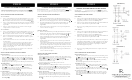
1. To install glass, slip tube (1) over threaded stem (2) on bottom of
fixture body – see Drawing 2.
2. Slip cap (3) over threaded stem (2) followed by cap (4).
3. Slip threaded stem (2) through center hole of glass (6) and hold
glass in position.
4. Slip plastic washer (7) followed by steel washer (8) onto threaded
stem (2) and hold parts in position.
5. Thread hex nut (9) onto threaded stem (2) and tighten hex nut to
secure glass.
7. Lift decorative ring (12) up around glass and rest tabs (t) on top of
the glass.
1. Para instalar vidrio, tubo de deslizamiento (1) sobre el vástago
roscado (2) en la parte inferior del cuerpo xture fi - ver Dibujo 2.
2. casquillo de deslizamiento (3) sobre el vástago roscado (2) seguido
por el anillo (4).
3. Deslice vástago roscado (2) por el orificio central de cristal (6) y
mantenga el vidrio en su posición.
4. Deslizamiento de plástico arandela (7), seguido de arandela de
acero (8) sobre el vástago roscado (2) y mantener las piezas en su
posición.
5. Tema tuerca hexagonal (9) en el vástago roscado (2) y apriete la
tuerca hexagonal para asegurar el vidrio.
7. Levante el anillo decorativo (12) alrededor de vidrio y descansar
pestañas (t) en la parte superior de la copa.
1. Pour installer le verre, le tube de glissement (1) sur la tige filetée
(2) sur le fond du corps de xture fi - voir schéma 2.
2. bouchon de glissement (3) sur la tige filetée (2) suivie par l'anneau
(4).
3. Glissez la tige filetée (2) dans le trou central du verre (6) et
maintenez le verre en position.
Rondelle de plastique 4. Slip (7), suivie par l'acier rondelle (8) sur la
tige filetée (2) et maintenir les pièces en position.
5. Visser l'écrou hexagonal (9) sur la tige filetée (2) et serrer l'écrou
hexagonal pour sécuriser verre.
7. Soulevez anneau décoratif (11) autour du verre et de repos onglets
(T) sur le dessus du verre.
10
11
6. Slip bottom cap (10) onto threaded stem (2) and hold
in position while threading on bottom knob (11).
6. Deslice tapa inferior (10) en el vástago roscado (2) y mantenga en su
posición mientras enhebrar la perilla inferior (11).
6. Faites glisser le capuchon inférieur (10) sur la tige filetée (2) et
maintenir en position pendant le vissage sur le bouton en bas(11).