
Installation Owner manual


SYSTEM WIRING Page 7 - 27 7
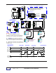
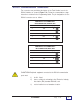
Order I/O (Input/Output) modules separately from the TS-IEM module. Output
modules are equivalent to either a single pole single throw, normally open
contact (FORM-A, SPST-NO Make ), or normally closed (FORM-B, SPST-NC,
Break ) contacts. Input modules exist in two versions: AC and DC.
See TABLE 7-5 (which follows the installation and wiring diagrams) for a listing
of available choices.
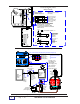
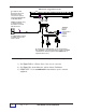
Figure 7-13b. TS-IEM Internal Expansion Module Installation
NOTE
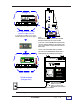
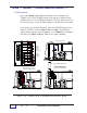
I/O MODULE (INPUT MODULE SHOWN)
Space for
Internal
Expansion
I/O Module
# 1
Space for
Internal
Expansion
I/O Module
# 2
J1 DISPLAY & KEYPAD
CAB LE TO J6
NOTE:
The first TS-IEM Module
is installed at the upper left corner
of the TS-2001 console and plugs
into J12. This is the installation
location for consoles with one TS-IEM.
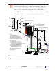
Field Installation Steps
1) Install the standoffs as shown
2) Use two #8-32 x 3/8 inch (9.5 mm) hold-down
screws at the right side, and the
two 3 inch (76.2 mm) standoffs at the right side
of the module,
3) Install wiring (see Wiring Diagram)
4) Install the Safety Shield with the
remaining two hold-down screws
The second TS-IEM Module is installed
at the lower left side of the console
and plugs into J10.
J2
+DC-
MT
IN / O U T 5
IN / O U T 6
IN / O U T 7
IN / O U T 8
+DC- +DC-
AC
+DC- +DC-
ACACAC
MT
IN / O U T 1
IN / O U T 2
IN / O U T 3
IN / O U T 4
AC
+DC- +DC-+DC-
ACACAC
MT
170- 10 58
RL7
RL8
RL6
RL5
J1
RL4
RL3
RL2
RL1
MT
CLEAR TERMINAL SAFETY-SHIELD
3 INCH (76.2 mm) STANDOFF (2)
MAIN
SYSTEM
PC Bd
J22
U50
J5
U47
J9
J4
J11
U35
J1 0
DTR
D13
J8
S1
TXD
D12
J7
U36
J21
DCD
RXD
D15
D14
D2
170-1054
J3
J6
U45
J32
TP3
J1
J12
U10
J2
TS-1001 /N-N U10
VER No. DATE
TS-IEM Module PC Board
1 INCH (25.4 mm) STANDOFF (2)
TP1
TP2
J33
# 8-32 x 3/8 INCH (9.5 mm) SCREW (4)
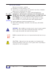
WARNING:
LETHAL VOLTAGES COULD EXIST !
LOCAT E AND DISCONNECT ALL EXTERNAL POWER SOURCES
BEFORE WORKING ON OR SERVICING THESE CIRCUITS —
REINSTALL THIS COVER BEFORE OPERATING EQUIPMENT.
(
T2
)