
User Manual


TOC
Page TOC - 4 Tank Sentinel Operator’s Guide
Routine Maintenance ........................................................................................... 5 - 14
• External Cleaning ..................................................................................... 5 - 14
• Replacing the Printer Paper Roll............................................................... 5 - 14
• Lubricate Printer: ...................................................................................... 5 - 14
• Replacing Fuses, Memory-backup Battery, & Interior Cleaning:.............. 5 - 15
FCC Information & Requirements ........................................................ FCC - 1
Overall Information & Requirements ................................................................ FCC - 1
INDUSTRY CANADA Information & Requirements ...................................... FCC - 2
CP-01 Issue 8, Part I, Section 14.1 .................................................................. FCC - 2
CP-01, Issue 8, Part I, Section 14.2 ................................................................. FCC - 2
G Glossary .............................................................................................. G - 1
CFF Customer Feedback Form....................................................... CFF - 1
W Warranty .............................................................................................. W - 1
Table of FIGURES and TABLES
Graphic Symbol Conventions .................................................................... P - i
Page Numbering Convention – Example:................................................. P - i
Page Layout Convention – Example: ........................................................ P - i
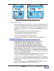
Figure P - 1 TS-1001 & TS-2001 Model ATG Consoles......................... P - iii
Figure 1 - 1 Console Component Identification ...................................... 1 - 2
TABLE 2.1 Output Groups (A — FF)..................................................... 2 - 6
Figure 2.1 External BriteBoxes to Console ......................................... 2 - 7
Figure 2.2 Typical Station Partial Side-view with One Tank ................. 2 - 7
TABLE 2.1 Output Groups (A — FF)..................................................... 2 - 8
Setup Report (example) .......................................................................... 3 - 23
TABLE 5 - 1 Alarms & Error messages ................................................ 5 - 1
TABLE 5 - 2 SYSTEM TEST SCHEDULE ............................................ 5 - 7
TABLE 5 - 3 Fax Numbers & Location (Fill-in)....................................... 5 - 11
—
❖
—