
User Manual


1
Page 1 - 2 Tank Sentinel Operator’s Guide
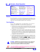
M
ODEL
:
TS-1001
S/N:
121795
120
VAC, 50 / 60 Hz
A
MPS
M
AX
:1
INTELLIGENT CONTROLS, INC. SACO, ME 04072 USA
AUTOMATIC
TANK GAUGE
&
LEAK
DETECTION
SYSTEM
MADE IN
USA
Tank Sentinel
®
PN 240-1187
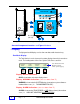
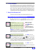
Figure 1 - 1. Console Component Identification – TS-1001 shown typical
Console Component Location – see Figure 1-1 above
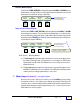
➀
Display
The light-green backlit display consists of two rows that are 40 characters long.
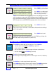
Run Mode Display
The Tank Sentinel console shows up to four status-display columns in the normal run
mode. The heading names of these are: System, Tank, Sensor, and Line.
Display Normal Indications
OKAY is shown under each status-display column.
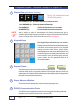
Display WARNING Indications ( also see Status Row ➂ )
WARNING is shown under the SYSTEM display column when a system software or
hardware failure occurs ( i.e. FAX HARDWARE FAILURE )
Display ALARM Indications ( also see Status Row ➂ )
ALARM is shown under a
TANK
, SENSOR, or LINE display column(s) when alarms
occur ( i.e.
HIGH LIMIT
, HIGH BRINE, 0.2 GPH LINE LEAK )
Door hinge
(left side)
TS -1001
TANK SENTINEL
®
See Tank and Line
Display Notes
a & b (next page)
SYSTEM TANK SENSOR LINE
OKAY OKAY OKAY OKAY
M1 M2 M3 M4
LEFT RIGHT