Tank Sentinel® Operator’s Guide TS-1001, 2002, 504, 508 & 750 Automatic Tank Gauge/ Leak Detection System 3760 Marsh Road ● Madison, WI 53718 U.S.A. Tel: +1 608 838 8786 ● Fax: +1 608 838 6433 ● www.franklinfueling.com Tel: USA & Canada 1 800 225 9787 ● Tel: Mexico 001 800 738 7610 Part Number: 000-1052, Rev.
NOTICE Franklin Fueling Systems has strived to produce the finest possible manual for you, and to ensure that the information contained in it is complete and accurate. However, Franklin Fueling Systems makes no expressed or implied warranty with regard to its contents. Franklin Fueling Systems assumes no liability for errors or omissions, or for any damages, direct or consequential, that result from the use of this document or the equipment which it describes.
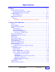
Table of Contents P Preface ................................................................................................... P - i Graphic Symbol Conventions ............................................................................... P - i Page Numbering Convention – Example: ....................................................... P - i Page Layout Convention – Example: .............................................................. P - i Product Overview ..............................................
2 Acknowledging Alarms ........................................................................ 2 - 1 Purpose of Audio / Visual Alarms .......................................................................... Audio Alarm Annunciator (& Output Relays) ......................................................... Visual Alarm Indications ........................................................................................ Alarm Types ............................................................................
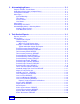
Cleared Tank Alarms REPORT ..................................................................... Tank Alarm History REPORT ....................................................................... Active Sensor REPORT ............................................................................... Cleared Sensor Alarms REPORT ................................................................. Sensor Alarm History REPORT ....................................................................
Routine Maintenance ........................................................................................... • External Cleaning ..................................................................................... • Replacing the Printer Paper Roll ............................................................... • Lubricate Printer: ...................................................................................... • Replacing Fuses, Memory-backup Battery, & Interior Cleaning: ..............
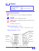
P PREFACE Contents: Graphic Symbol, Page Numbering and Layout Conventions Product Overview Alarms and Warnings Tank Sentinel Features Safety Approvals Need Help ? Names and Phone Numbers to Contact Graphic Symbol Conventions NOTE ☞ Important information, tips, and hints are highlighted by the NOTE graphic. CAUTION or WARNING messages are highlighted by this graphic. DANGER messages are highlighted by this graphic and contain instructions that must be followed.
Product Overview ® The INCON TS-1001 / 2001 /504 / 508 / 750Tank Sentinel consoles are complete leak detection and inventory monitoring systems. The TS-750 / 1001 / 2001 models run in-tank leak tests with exceptionally high accuracy. The TS-504 / 508 models are designed for monitoring and controlling liquid levels in aboveground storage tanks. Liquid Level Probe & The tests meet or exceed all current EPA standards.
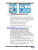
TS-2001 TANK SENTINEL® TS-1001 TANK SENTINEL® Figure P - 1 TS-1001 & TS-2001 Model ATG Consoles Alarms and Warnings – Alarms and warnings are designed to alert you / make you aware of a problem when it occurs so you can take appropriate corrective action. System hardware fail warnings, tank related alarms, leak detection sensor alarms, and line leak alarms can be customprogrammed to do many things.
Tank Sentinel® Features (CONTINUED... ) • • • • • • All consoles can communicate with remote computers for off-site notification, management, and dispatch requests with the optional data or fax modem. Access to the Tank Sentinel console door is key-locked for security, and the database / setup-configuration program mode can be protected by security passwords to protect the operation and function of the tank gauge.
1 Console – Basic Operation Contents: Operating Modes, Component Location Display (Run Mode, Normal Warning and Alarm Indications, Sentinel Mode, Tank or Line Testing) Menu Keys (M1 – M4), Status Row & Alarm Test key, Keypad Keys, Optional Report Printer, Paper Advance-Button, RS232 CommunicationPorts, TS-FM1/TS-DOM Receptacle, Model & Serial No. Label, Product & Tank-Related Keys: PRODUCT, GROSS, LEVEL, TANK, ULLAGE, WATER Menu-Related Keys: CANCEL, UP, DOWN, ENTER, MENU Special Keys: ALARM, REPORT...
TS -1001 TANK SENTINEL ® Tank Sentinel ® AUTOMATIC TANK GAUGE M ODEL : TS-1001 120 & 121795 VAC, 50 / 60 Hz AMPS MAX: 1 LEAK DETECTION SYSTEM MADE IN USA PN 240-1187 S/N: INTELLIGENT CONTROLS, INC. SACO, ME 04072 USA Door hinge (left side) Figure 1 - 1. Console Component Identification – TS-1001 shown typical Console Component Location – see Figure 1-1 above ➀ Display The light-green backlit display consists of two rows that are 40 characters long.
Sentinel Mode Display Under the word TANK, SENTINEL is alternately displayed with OKAY or ALARM when the Sentinel mode is running. Sentinel-mode is programmed to run after business hours and will monitor for product thefts and gross tank leaks.
Component Location 3 ( Continued...
➇ TS-FM2 Receptacle Remote communications (telephone) port for the optional internal Data Only Modem or Fax Modem (TS-FM2). After a fax/modem is installed and the communications program is setup, modem data can be sent to up to 4 different numbers in response to deliveries, alarms, or leak test results.
Product & Tank Related Keys ( CONTINUED... ) D SELECT TANK TANK 1 Q TANK 4 TANK 2 TANK 3 TANK 4 REGULAR TANK 1 GROSS NET WTR VOL 22080 21855 93.3 ULLAGE 2020 REGULAR TANK 1 LEVEL TEMP WTR LVL 98.25 67.8F 1.8 PERCENT 93.5 Press DOWN for other tanks & Press a menu key to select a tank Press DOWN to see additional tank data ...
Menu Related Keys ( CONTINUED... ) ENTER H The ENTER key has many uses. Press ENTER to: • accept a setup menu choice or input value for storage into memory • accept or to change the number of reports to print (to save paper) • accept an alphanumeric code input...
Menu Related Keys ( CONTINUED... ) Changing the Display and Report Language H U MENU Press the MENU key and then the M3 menu key. Choose the language that you want to use (English is the default language), and then press the menu key ( M1 M2 M3 or M4 ) directly under the desired language ...changes are immediate.
Special Keys ( ALSO SEE THE GLOSSARY ) I V SELECT ALARM TYPE SYSTEM TANK SENSOR (MORE) LINE ALARM 8 M1 M2 LEFT RIGHT M3 SELECT ALARM TYPE ALL M1 M2 LEFT RIGHT M4 (MORE) M3 M4 SELECT SENSOR ALARM STATUS ACTIVE CLEARED HISTORY NOTE ☞ J W M1 M2 LEFT RIGHT M3 M4 (MORE) = press the DOWN key to display more choices Press a menu key under one of these types to display a status group to choose from (Active, Cleared, or History).
Report Features See Chapter 3 ...Reports may be programmed or scheduled to print automatically at certain times (for example, during work shifts, every day, every week on a particular day, or every month on a particular day). Other reports can be automatically fax’d or printed when an alarm occurs, or when a non-alarm event happens (for example, when the result of a Leak Test is available). M Z SELECTFUNCTION 07:16:47 PM 12-23-1997 DISPLAY PRINTER DIALTONE OPTIONS CHECK .
Special Keys ( Continued... ) L SELECTLEAKTESTOPTION STATUS START Y ABORT TEST 0 M1 M2 LEFT RIGHT M3 M4 1) Press the TEST key and then the M2 key (above) 2) Choose the type of test below (press a menu key) SELECTLEAKTESTTOSTART 0.1TANK 0.2TANK M1 M2 LEFT RIGHT M3 M4 3) Choose the Tank or Line # (press a menu key) SELECTTANKTOSTART0.2TEST (MORE) TANK1 TANK2 TANK3 M1 M2 LEFT RIGHT TANK4 M3 M4 4) Choose ALL – press DOWN and then the M1 key SELECTTANKTOSTART0.
Special Keys ( Continued... ) L Y Aborting a Tank or Line Leak Test SELECT LEAK TEST OPTION STATUS START ABORT TEST 0 M1 M2 LEFT RIGHT M3 M4 An abort is used to cancel a test... a test must be aborted before a different type of leak test can be started. 1) Press the TEST key and then the M3 key (above).
RELAYS AND ANNUNCIATOR ACKNOWLEDGED GRACE PERIOD STARTED ACK SHIFT M1 M2 LEFT RIGHT M3 M4 ACK is an abbreviation for alarm acknowledge. The ACK SHIFT key is a special key with many uses. ACK SHIFT key uses: 1) Silence alarms (Press ACK SHIFT / input an Alarm Acknowledge password if required) 2) Acknowledge alarms (see Chapter 2) 3) Start a programmed Grace Period (if output modules are installed in the console or a TS-CIM BriteBox, or if a TS-ROM BriteBox is installed... see Figure 2.
Upgrade Menu Additional features can be added by Ordering a TS-UPGRADE (For example, a TS-FM2 Fax Modem can be added). Hardware must be added to the Tank Sentinel system just before the upgrade is performed. Because setup programming is required once an upgrade is performed, INCON recommends that you contact your service provider to perform all upgrades for you.
Sample Upgrade Instructions (Page 1 of 2) INTELLIGENT CONTROLS INC 74 INDUSTRIAL PARK RD http://www.intelcon.com SACO ME 04027 U S A Sample TS-UPGRADE Tank Sentinel 000-1368 Rev. B Field Upgrade Instructions Here is the field upgrade you purchased for the Tank Sentinel listed below. Please take a moment to read the instructions before you begin the upgrade process. Note: Some upgrades require new hardware to be installed in the Tank Sentinel (e.g. printer, modem... etc.).
— Your Notes — — ❖ — 1 Page 1 - 16 Tank Sentinel Operator’s Guide
2 Acknowledging Alarms Contents: Purpose of Audio / Visual Alarms Audio Alarm Annunciator (& Output Relays) Visual Alarm Annunciators (& Indications) Alarm Types (System Warnings, Tank Alarms, Sensor Alarms, Line Alarms) Alarm Status, Acknowledge Password, Acknowledging Alarms / Silencing Alarms Starting a Grace Period Leak Detection Sensors Tables and Figures Purpose of Audio / Visual Alarms Audio / Visual alarm annunciators are designed to alert you of a problem so appropriate and immediate corrective
Visual Alarm Indications The console has 4 visual output devices: 1) Light green, 80 character display 2) Yellow warning light (Status Row) 3) Red alarm light (Status Row) 4) Printer reports – printout if enabled / programmed and if the printer has paper The console display will show a WARNING message under the word SYSTEM when a system fault occurs. An ALARM message will appear under one of the TANK or SENSOR or LINE columns when one of those alarms happen.
Alarm Types System Warnings Are alarms that are caused by equipment failures or software malfunctions. These could also be transient, instantaneous failures or warnings of impending failures. Do not ignore system warnings! See Chapter 5 for Site Policy & SYSTEM warnings in TABLE 5 - 1. Tank Alarms Occur when a tank-related programmed limit is reached. See Chapter 5 about Site Policy & about TANK alarms (in TABLE 5 - 1).
Acknowledge Password For a variety of reasons, some sites may be programmed with a special Alarm Acknowledge Password. This code must be entered correctly at the keypad before an alarm can be acknowledged / silenced. Acknowledging Alarms / Silencing Alarms • Status row lights are flashing... To view the cause of the alarm....
Leak Detection Sensors T SP-EIS TSP-EIS Electro-optic Interstitial (3 wire, infrared) Standard Sensor detects liquids in spaces between the walls of DWTs T SP-ULS TSP-HLS TSP-HLS High product Level (2 wire, float switch) Standard Sensor used inside of tanks as an overfill alarm detector (or in addition to the HIGH, and HIGH HIGH probe limits) TSP-ULS Universal Liquid Sensor (2 wire, float switch) Standard Sensor detects liquids in: spaces between the walls of DWTs or Dispenser sumps T SP-DIS 3 wire B
You must know what corrective actions / steps to take when a leak test fails, when a leak detection sensor alarms, or when other problems or faults occur. These steps may differ according to your location (Country, State, Province, City or local codes). Alarms and limits may be programmed to one of the 32 available Output Groups (A thru FF). Reference your system and tank Setup Report for these associations. TABLE 2.
Of the 4 BriteBoxes that can connect to a Tank Sentinel system: 1 or 2 can be TS-SEM Sensor Expansion Modules 1 can be a TS-ROM Relay Output Module, and 1 can be either a TS-TGI Tank Gauge Interface module, or a TS-CIM Control I/O Module I/O M ODULE T S-CIM / T S-T GI B RIT EB OX T S-ROM BRIT E BOX TANK GUAGE I NT ERFA CE M ODUL E T S-S EM BRIT EB OX #2 REL AY OUTP UT M ODUL E TS-T GI INPUT S FROM S IGNA L DEV ICES OUT PUT S T O LOAD DEV ICE S ® T S-S EM BRIT EB OX #1 SENSOR EXP ANSI ON M ODUL E T
TABLE 2.1 – Output Groups (A — FF) Continued... Probe / Sensor Name /Type Location Channel Limit Alarm OG Group Action 20 22 23 24 25 26 27 28 29 30 31 32 33 34 35 36 37 38 39 40 example TSP-DIS Tank 4 12 Product 12 CP Disp.
— Your Notes — — ❖ — Acknowledging Alarms Page 2-9 2
3 Tank Sentinel Reports Contents: Reports Overview & Types How to Print a Report FAXing a Report Sample Reports Product Inventory (detail & summary) Tank Inventory (detail & summary) Product Delivery (detail, summary, history) Product Usage (detail, summary, reconcile) Tank Leak Test Estimate, Static Test, SCALD Leak Test, Line Leak Test (compliance) Sensor (status & vapor), Alarm Reports (active cleared system line) Setup (system, tank) Regulatory, Generator Run, & Print Test Reports Overview Reports ma
How to Print a Report (steps): SELECT REPORT GROUP INVENTORY DELIVERY M1 M2 LEFT RIGHT SELECT REPORT GROUP SENSOR ALARM M1 M2 LEFT RIGHT SELECT PRODUCT DETAIL SUMMARY M1 M2 LEFT RIGHT (MORE) TEST USAGE M3 (MORE) SETUP REGULATORY M3 M1 M2 RIGHT J W key REPORT 9 M4 2) Press the DOWN key to show more choices when UP / DN or MORE is displayed M4 SELECT TANK DETAIL SUMMARY M3 3) Press menu keys ( M1 — M4 ) to make a selection M4 MIDGRADE - INVENTORY DETAIL REPORT PRINTER FAX LE
Example – Automatic Alarm Reports Alarm Reports printout automatically when they happen (the default setup enables automatic printing for ALARMS, LEAKS, SCALD, LINES, or Generator runs) Typical Information Shown On Reports REPORT HEADER is printed first and shows the site location data...
Sample Reports Product Inventory Detail REPORT Shows the: Product Name (UNLD REG = unleaded regular gasoline), and Capacity (volume units shown are gallons) Gross product volume (not temperature compensated) Net product volume (temperature compensated), Days Supply remaining (calculation based on use), and Water Volume (petroleum fuel oil / gasoline applications using two floats – only) ...
Tank Inventory Detail REPORT This report shows the Volume & Level data by tank ...2 tanks shown typical. Shows the: Tank Name Tank NO.
Sample Reports (CONTINUED... ) Product Delivery Detail REPORT Shows all data relative to product deliveries for a Tank. It includes the Product Name, Tank Capacity, Tank Name, beginning Time and Tank conditions before (BEGIN values) and after delivery (END values). One Tank is shown in this example. Press: J Press: W REPORT 9 + Report Choices M2 Delivery Reports: Detail Summary History M1 Product Name ...Prod N All Choose Printer or Fax M2 Product Name ...
Product Usage Detail REPORT Shows the Gross and Net inventory, Days Supply remaining, Ullage to fill to capacity. Usage per Day, Week and Month are also detailed for a selected product. Combined values will be shown when a manifold physically connects two or more tanks. Note: Last Usage REJECTED means that insufficient data has been collected before this report was printed.
Sample Reports (CONTINUED... ) Product Usage Reconcile REPORT ( Inventory Reconciliation REPORT ) Balances inventory based on starting inventory, ending inventory, and deliveries. The report shows all data for a Tank including the Product Name, Tank Capacity, Tank Name, beginning Time and Tank conditions before (BEGIN values) and ending (END values). The report shows usage which can be used to check against (reconcile) meter readings.
Product Usage Sales REPORT The Tank Sentinel DIM/Reconciliation option supports Printing, Faxing and Transmission via a Serial Connection Reconciliation reports that include Sales Volume data collected from an attached TS-DIM unit. INCON INTELLIGENT CONTROLS INC. P.O. BOX 638 SACO ME 04072 1-800-984-6266 3/12/2002 The Sales Dollars Reports Feature adds the capability to Print, Fax and Send via a Serial Connection Sales Dollars reports.
Sample Reports (CONTINUED... ) Tank Leak Test Estimate REPORT Shows the estimated amount of time to complete a Standard / Static Tank Leak Test if started immediately. Estimates are affected by the size and type of tank, and conditions within the tank (such as changing product temperature because of a recent delivery, or surface ripples / disturbances from a recent dispense or delivery). It also gives the time remaining for a test if this is run during that test.
Standard (Static) Tank Leak Test REPORT The data shown on the standard leak test report is: 1) Date and time that the report was produced (this can be different from the test End Time and Date. 2) Tank name, number, and volume capacity (GAL). Then the Leak Test Precision & Threshold is shown (0.1 gph Annual Precision test — the default is the 0.2 gph monthly compliance test). 3) Test Confidence Level (here @ 99%... there is still a 1 % chance that the results are not accurate).
Sample Reports (CONTINUED... ) SCALD Leak Test REPORT SCALD is an acronym for Statistical Continuous Automatic Leak Detection. This test is typically used at sites that dispense 24 hours a day, where leak testing can only be done between dispenses. It runs a 0.2 gph Monthly Regulatory Compliance Test.
Line Compliance Test REPORT (Intentionally shown out of position.) This report will include one years worth of 0.2 gph monthly compliance tests for a selected line, or all lines... the most recent test is shown first and the oldest last. After a year, the oldest test will be dropped when a new test passes.
Sample Reports (CONTINUED... ) Line Leak Test REPORT This report will show the latest line leak tests for a selected line or all lines... the number of passed 3 gph line leak tests that passed today is shown first and is followed by the most recent 0.1 or 0.2 gph line test result. Note: Leak Rate is affected by many factors and is provided for diagnostic purposes. Line Leak Diagnostic REPORT Not shown... this report is used by technicians to diagnose problems.
Line Leak Test History REPORT Tank Sentinel Reports Page 3 - 15 3
Sample Reports (CONTINUED... ) ...Shown in FAX format (page 1 & 3). The last 10 pass or failed line leak tests are shown per line. Report(s) Sent to Remote Fax Machines: When properly setup, reports can be sent automatically or manually to as many as four different fax machines. Faxes are arranged in a two column format, and will fit on as many pages as necessary (as shown here). For example, Setup and Regulatory Reports are lengthy and take many pages to finish.
Sensor Status REPORT Shows the Sensor name, the sensor input-channel number, and the current status of each sensor that is wired to the system (OK or ACTIVE in alarm / leak detected). Also, CVS data will be shown on the report when CVS has been programmed (enabled). INCON INTELLIGENT CONTROLS INC. P.O. BOX 638 SACO ME 04072 1-800-984-6266 Press: 04/30/2002 J SENSOR STATUS REPORT SENSOR NO. 1 SENSOR 1 OK : : SENSOR NO. 7 SENSOR 7 STANDARD SENSOR SENSOR NO.
Sample Reports (CONTINUED... ) Press J W REPORT Alarm Reports 9 K + Active System Alarms REPORT Not shown... reports active system warnings, alarms, and software — or equipment hardware — failures, faults, and errors. The date, time of the alarm, and the alarm name are shown (typical). X DOWN SPACE M2 Alarm Reports: System M1 Active Cleared History * Not shown... reports the system alarms that have cleared.
Press J W REPORT Alarm Reports (Continued... ) 9 K + Active Sensor REPORT Not shown... reports active sensor alarms... The date, time of the alarm, and the alarm name are shown (typical). X DOWN SPACE M2 Alarm Reports: System M1 Not shown... cleared sensor alarms only.
Sample Reports (CONTINUED... ) Alarm Reports (Continued... ) All Active Alarms REPORT Reports all active system, tank, sensor, and line alarms. The date, time of the alarm, and the alarm name are shown (typical). The most recent alarms are shown first. TSP-HIS BriteSensor 8 (Channel # 8) is in alarm (Low Brine Level). Printer is Out of Paper alarm. Standard Sensor 7 (Channel # 7) is in alarm. Tank 1 (high product level) alarm.
Alarm Reports (Continued... ) All Alarm History REPORT Shows the history of all active, cleared and transient alarms for all alarm types (System, Tank, Sensor, Line, or ALL). The example to the left is an ALL — Alarm History report. It can hold up to 50 alarms in the alarm history memory buffer. The total number of alarms to print can be reduced to conserve paper ...please see the Changing the Number of Reports to Print topic earlier in this Chapter).
Sample Reports (CONTINUED... ) System Setup REPORT The System Setup report shows the full configuration of the Tank Sentinel console. It includes most of the information found in a tank setup report except for special tanks strapping tables (tank chart) and information on special tanks and products. See the following Tank Setup Report. See an example system setup report on the following pages. Tank Setup REPORT Tank Setup Reports are available for each tank in the system.
Setup Report (example) Tank Sentinel Reports Page 3 - 23 3
Setup Report (example) 3 Page 3 - 24 Tank Sentinel Operator’s Guide
Setup Report (example) Tank Sentinel Reports Page 3 - 25 3
Setup Report (example) 3 Page 3 - 26 Tank Sentinel Operator’s Guide
Regulatory REPORT This report can be sent to the regulatory agency for compliance verification. It shows the hardware status of equipment that is part of the INCON Tank Sentinel system. The last 12 months of PASSED Static and SCALD tank leak tests, and passed 0.2 gph line tests are shown. In addition, the last 0.1 gph annual precision line leak tests for all lines are shown. Also see Leak Test and Line Compliance Test reports.
Sample Reports (CONTINUED... ) CPM Alarm Report The CPM alarm report (at right) is generated when the current level is below the setpoint, which is programmed. A CPM failure will be produced if communication is lost between the tank gauge and the TS-CPM unit (this may also be a result to the TS-CPM loosing power). Alarm report(s) will only be produced when SETUP> SYSTEM> REP ALARM> (report alarms) is ENABLED. INCON INTELLIGENT CONTROLS INC. P.O.
CPM Monthly Report The Regulatory Report now includes a Monthly CP Status Report, which is updated on the first day of every month. Up to 12 months of Monthly CP reports are included in the Regulatory Report (CPM must be enabled). INCON INTELLIGENT CONTROLS INC. P.O. BOX 638 SACO ME 04072 1-800-984-6266 3/12/2002 This report is available on demand for printing at the tank gauge printer, or for faxing, or it can be sent via modem to a site when the Regulatory Report is programmed properly.
Sample Reports (CONTINUED... ) Generator Run REPORT This report shows when the generator started (BEGIN) and stopped (END) and the fuel consumed (USAGE & USAGE RATE) during the run. This report is available only with consoles that have the special Emergency Generator application software. INCON INTELLIGENT CONTROLS INC. P.O. BOX 638 SACO ME 04072 1-800-984-6266 6/17/2002 2:15 PM Press: GENERATOR RUN REPORT Press: INPUT TANK 1 AUXILIARY 1 3918.
— Your Notes — — ❖ — Tank Sentinel Reports Page 3 - 31 3
4 Leak Testing Contents: Leak Testing — Overview Tank Leak Tests – Type and Frequency Requirements — Before Starting a Tank Test When to Run Tank Leak Tests Starting Tank Leak Tests Tank Leak Test Results Reasons Why Tank Leak Tests can Fail TS-LLD Line Leak Tests Type and Frequency Requirements, When to Run Line Leak Tests Starting Line Leak Tests When a Line Leak – Test Fails / is Detected Steps to take When a Line Leak is Detected Need Help ? All INCON Tank Sentinel models meet (or exceed) the require
Tank Leak Tests – Type and Frequency Two standard leak tests can be started from the keypad, they are the 0.2 gph and the 0.1 gph test. Federal, State and local codes and regulatory agencies specify how often to run these tests. Consult and comply with these rules and regulations. CAUTION It is the tank owner’s obligation to comply with the procedures and the reporting requirements of federal, state and local regulations. Your are legally bound to follow these explicitly.
Starting Tank Leak Tests: Follow the steps below: L Y SELECT LEAK TEST OPTION STATUS START ABORT TEST 0 M1 M2 LEFT RIGHT M3 M4 1) Press the TEST key and then the M2 key (above) 2) Choose the type of test below (press a menu key) ...choices are the 0.1 gph or 0.2 gph leak tests: SELECT LEAK TEST TO START 0.1 TANK 0.2 TANK 0.1 LINE M1 M2 LEFT RIGHT M3 0.2 LINE M4 3) Choose the Tank # (press a menu key below): SELECT TANK TO START 0.
Reasons Why Tank Leak Tests Fail (Continued... ) • Large changes in product temperature (from start to end of the test). • Water Level changes (from start to end of the test). • Evaporation and loss of product – through the vent stack – will look exactly like a leak. Evaporation can be a problem during high seasonal temperatures and/or high winds, & when liquid level exposes the greatest surface area for evaporation (half full tanks are worse).
WARNING You (the tank owner) are legally obligated to comply with the reporting and procedure requirements of federal, state and local regulations. These must be followed explicitly. Serious legal, health and safety hazards could result from not taking immediate and proper action. Where the codes and regulations conflict with this manual — follow the regulations. NOTE Reference TABLE 5 - 2 for a blank Test Schedule that you can copy and use for Tanks, Lines, etc..
Starting Line Leak Tests L Y SELECT LEAK TEST OPTION STATUS START ABORT TEST 0 M1 M2 LEFT RIGHT M3 M4 1) Press the TEST key and then the M2 key (above) 2) Choose the type of test below (press a menu key) ...choices are the 0.1 gph or 0.2 gph leak tests: SELECT LEAK TEST TO START 0.1 TANK 0.2 TANK 0.1 LINE M1 M2 LEFT RIGHT 0.2 LINE M3 M4 3) Choose the Line # (press a menu key below) SELECT LINE TO START 0.
Steps to take When a Line Leak is Detected: Reference the policy and procedures at you site / Chapter 5. 1) Identify what type of leak was detected 2) Stop / Prevent dispensing (bag or tape poly over dispenser & dispense lever). 3) Inspect the piping system, dispenser, fittings, and hoses for obvious leaks. Open the dispenser enclosure, and inspect the fittings and fuel filter for leaks (this is especially important if maintenance or service was done recently).
— Your Notes — — ❖ — 4 Page 4-8 Tank Sentinel Operator’s Guide
5 TroubleShooting & Routine Maintenance Contents: Silencing Alarms Troubleshooting Alarms & Error messages, (see ACK key – Chapter 1, and Line and Tank Leak Test Failures Acknowledging Alarms Chapter 2) Call Numbers & FAX No’s (TABLE 5 - 3) ) Alarms & Error Messages (TABLE 5 - 1) DO Before & After Installation / Upgrade System Test Schedule (TABLE 5 - 2) Site Sketch Important Policy & Procedures at Your Site Routine Maintenance (External Cleaning, (Silencing Alarms, Acknowledging Alarms, Replacing Printer
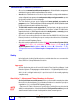
TABLE 5 - 1 (CONTINUED... ) ALARMS & ERROR MESSAGES NOTE: Diagnostic text in the left column, is shown bolded { become alarms if active for 48 hours } # Printed / Faxed / Displayed Alarm / Warning Text: 9 LSU COMM/LSU COMM FAILURE LINE (Push RESET / TEST button on the TS-LLD control unit that is flashing an 83 Alarm-error code and call for service).
TABLE 5 - 1 (CONTINUED... ) ALARMS & ERROR MESSAGES NOTE: Diagnostic text in the left column, is shown bolded { become alarms if active for 48 hours } # Printed / Faxed / Displayed Alarm / Warning Text: 23 AUXILIARY INPUT SENSOR Auxiliary input detected on channel 1 or 2 (follow policy procedure at your site).
TABLE 5 - 1 (CONTINUED... ) ALARMS & ERROR MESSAGES NOTE: Diagnostic text in the left column, is shown bolded { become alarms if active for 48 hours } # Printed / Faxed / Displayed Alarm / Warning Text: 32 SUMP FULL 33 VAPOR DETECTED / VAPOR Alarm Type: System WARNING / Error Descriptions and ALARM Descriptions (actions to take) SENSOR TSP-DDS, -DTS BriteSensor @ Channel #N liquid...
TABLE 5 - 1 (CONTINUED... ) ALARMS & ERROR MESSAGES NOTE: Diagnostic text in the left column, is shown bolded { become alarms if active for 48 hours } # Printed / Faxed / Displayed Alarm / Warning Text: 44 FAX SND FAIL / FAX SND SYSTEM WARNING - Fax Send Failure... (check Dial tone, cable, call service provider... are the fax phone numbers correct ?) 45 FLOAT HEIGHT / FLOAT HT / FLT HT SYSTEM WARNING - Float Height - calculation Error (setup program error...
TABLE 5 - 1 (CONTINUED... ) ALARMS & ERROR MESSAGES NOTE: Diagnostic text in the left column, is shown bolded { become alarms if active for 48 hours } # Printed / Faxed / Displayed Alarm / Warning Text: Alarm Type: System WARNING / Error Descriptions and ALARM Descriptions (actions to take) 55 RTC FAILURE SYSTEM Real Time Clock has failed. Clock and Calendar settings are affected. Verify date and time are correct (use CHECK key). Change settings as needed. Cycle power.
TABLE 5 - 1 (CONTINUED...
TABLE 5 - 2 SYSTEM TEST SCHEDULE Date NOTE ☞ Monthly Hardware Check / Test Results: Pass / Operational Fail / Trouble Monthly Alarm Annunciator(s) Test Results Monthly Tank Compliance Leak Test Results (Tank N) Monthly Line Compliance Leak Test Results (Line N) Contact your Tank Sentinel service provider if a hardware check finds a problem. If a leak test fails, see Leak Testing Chapter 4 about leak testing before calling.
Site Policy: • Silencing Alarms (using the ACK SHIFT key — see Chapter 1)... Policy and Procedures at your site: • Acknowledging Alarms (see Chapter 2)... Policy and Procedures at your site: • Grace Periods (Allowed when, number of times, etc.) (see Chapter 2)...
• Troubleshooting Alarms & Error Messages (see TABLE 5 - 1)...
• Troubleshooting Alarms & Error Messages (Continued...) (see TABLE 5 - 1)... Policy and Procedures at your site: • Line and Tank Leak Test Failures Policy and Procedures at your site (Who to call and when to call...
• Call Numbers for Help Policy and Procedures at your site (Who to call and when to call...
Site Sketch / paste-in area: TroubleShooting & Maintenance Page 5 - 13 5
Routine Maintenance • External Cleaning Use a soft cloth, that’s moistened in a solution of mild detergent, to clean the outer surfaces of the console. • Replacing the Printer Paper Roll Replace the paper roll when colored stripes appear at the outer edges of the paper, or when a PAPER OUT warning is flashed at the console display...
Routine Maintainance continued ... • Replacing Fuses, Memory-backup Battery, & Interior Cleaning: NOTE ☞ Let your Certified Tank Sentinel service provider do this work for you ! Fuse Replacement Instructions See INCON document 000-0214 for Fuse Replacement Instructions. WARNING High Voltage(s) exist within the Tank Sentinel Console which could cause electrical shocks, injury, or death if all power is not turned off before working inside the console.
— Your Notes — — ❖ — 5 Page 5 - 16 Tank Sentinel Operator’s Guide
FCC Information & Requirements Contents Overall Information & Requirements INDUSTRY CANADA Information & Requirements CP-01 Issue 8, Part I, Section 14.1 CP-01 Issue 8, Part I, Section 14.2 Overall Information & Requirements This equipment complies with Part 68 of the FCC Rules. On the bottom of the equipment exterior, near the telephone and serial ports, there is a label that contains, among other information, the FCC Registration Number and the Ringer Equivalence Number (REN) for this equipment.
INDUSTRY CANADA Information & Requirements CP-01 Issue 8, Part I, Section 14.1 “NOTICE: The Industry Canada Label identifies certified equipment. This certification means that the equipment meets certain telecommunications network protective, operational and safety requirements as prescribed in the appropriate Terminal Equipment Technical Requirements document(s). The Department does not guarantee the equipment will operate to the user’s satisfaction.
G Glossary Contents: Glossary of Technical Terms (including Definitions and Explanations) ABORT Stop or cancel a leak test before it has finished. ACK An abbreviation for Acknowledge alarm. The ACK keypad key will silence alarms and is used to acknowledge (become aware of) the existence and type of alarm when it is viewed / displayed so that corrective action can be taken.
DWT An abbreviation for a Double Wall Tank. EPROM An abbreviation for: Electrically Programmed Read Only Memory computer chip. F An abbreviation for the Fahrenheit temperature scale. FLOAT One or two floats are installed on liquid level PROBEs. All floats are magnetized so the float position can be determined exactly along the length of the probe.
LEAKS Occur when holes develope in the tank wall or piping system, or when the seals around tank accesses or pipe fittings age. The probability of a leak increases with age. There are two types of leaks: 1.) Product contamination from high ground water levels, and 2.) Environmental contamination from product leaking out of a containment area / tank. Leaks pollute the environment and create serious health and safety hazards.
SEM (TS-SEM) An abbreviation for the external Sensor Expansion Module (BriteBox) for the connection of 8 leak detection sensors. SENSOR SYNC A term used to describe a loss of synchronous data from the leak detection sensor (usually because of a corroded, wet or broken cable wires, or a sensor failure). SENTINEL MODE The after hours coarse leak test and theft monitoring mode (start and stop time must be programmed). SETUP The programming / configuration mode of the Tank Sentinel console.
CFF CustomerFeedbackForm Your ideas and opinions are important ! Please help us improve our products, services, and documentation by filling out and answering this Customer Feedback Form. Then return it to Franklin Fueling Sytems. Franklin Fueling System Technical Support 3760 Marsh Road Madison, WI 53718 USA FAX #: 608-838-6433 Please print these two pages and fill out information about yourself and the products you have received. Use black ink and print clearly.
Sale and Supply Orders: Please circle (1 = no / poor, 2 = fair, 3 = okay, 4 = good, 5 = yes / excellent, N = don’t know) Your order was processed quickly 1 2 3 4 5 N You were treated professionally & with respect 1 2 3 4 5 N You received what you ordered on time 1 2 3 4 5 N Sales Suggestions Technical Service / Support (Name of the service organization that you contacted ?): Please circle (1 = no / poor, 2 = fair, 3 = okay, 4 = good, 5 = yes / excellent, N = don’t know) Your call was p
WARRANTY INCON ® warrants its products to be free of defects in workmanship for a period of 12 months of operation from the date of installation, or 24 months from the date of shipment, whichever occurs first. Tank Gauge Software, OEM equipment, or non-serialized equipment that is sold by INCON (e.g. TS-M, and TS-MLS) are warranted for 90 days, parts only. During the warranty period, INCON will either replace or repair defective product at no charge.
Tank Sentinel Operator’s G uide