Tank Sentinel Programming Guide TS-5 Series Software Revision 0.5.0.7 Franklin Fueling Systems • 3760 Marsh Rd. • Madison, WI 53718 USA Tel: +1 608 838 8786 • 800 225 9787 • Fax: +1 608 838 6433 • www.franklinfueling.
Notice INCON strives to produce the finest manual possible and to ensure that the information that it contains is complete and accurate. However, INCON reserves the rights to change this document and specifications at any time without notice. INCON makes no expressed or implied warranty with regard to the contents of this manual. INCON assumes no liability for errors, omissions or for any damages, direct or consequential, that may result from the use of this document or the equipment that it describes.
Contents Notice.................................................................................................................................. ii Important Safety Messages............................................................................................... 1 Introduction......................................................................................................................... 3 FMS Functions...........................................................................................
Tank Sentinel Anyware (TSA)............................................................................................ 27 Navigating Applications Remotely............................................................................................. 27 Accessing Tank Sentinel Anyware.................................................................................................... 27 Making Changes to System Parameters...................................................................................
Important Safety Messages INCON equipment is designed to be installed in association with volatile hydrocarbon liquids such as gasoline and diesel fuel. Installing or working on this equipment means working in an environment in which these highly flammable liquids may be present. Working in such a hazardous environment presents a risk of severe injury or death if these instructions and standard industry practices are not followed.
Warning Substituting components could impair intrinsic safety. TS-5XXXs are intrinsically safe for sensors installed in – Class I, Division 1, Group D – hazardous locations. Substitution of components could make the energy limiting circuitry in the system ineffective and could cause an explosion hazard. Repairs to a TS-5XXX console or attached components should only be performed by a qualified, factory-trained technician.
Introduction The purpose of this manual is to guide installers, operators and technicians through programming and troubleshooting theTS-5 console, so that it’s configured based on a site’s specific needs. The Fuel Management Systems (FMS) application within the TS-5 Series consoles tie together the monitoring and alarm capabilities of preceding automatic tank gauges with advanced technologies to supply tank and level data more accurately and efficiently.
Definitions and Acronyms Module – A module is a plug-in card within the TS-5 series console that is used to perform various functions of the console. The modules are used for field wiring of the input and/or output of electrical signals between different functional equipment pieces. RS-232 – An IEEE standard for serial communication using a 9-pin connector. RS-485 – An IEEE standard for serial communication using STP/UTP wiring. RJ-45 – An IEEE standard connector for use in communications with STP wiring.
General After the Fuel Management System has been installed, typically your interaction with the system will be from the LCD display, on-board printer; or using TSA (Tank Sentinel Anyware) software to program and monitor the console remotely. Remote operation can be performed from a PC, either attached directly or through a network connection to the console. All of the features of the console are available through these input/output devices.
Password Input To modify console settings and change passwords, you must first enter in the current Administrator password. The default password is, in all lower case letters, “admin”. From the touch screen display, gaining Administrator privileges to perform high level functions with the console is done by navigating through the following menus to enter a password: 1. Once the console is powered up, press the Main Menu 2. Scroll down by pressing button. , and then press the Tools Application button. 3.
Configuring IP Settings for Communication Before attempting to modify any computer settings, contact the Information Technologies department of your business, if available. Some computer accounts may have restricted permissions to overcome before any changes are allowed to be made to TCP/IP settings. At the PC: 1. Power up the PC and log into your Windows operating system. 2. Click on Start, then select Control Panel. 3.
• In Classic View, click on Network Connections. 4. Right-click on Local Area Connection and select Properties.
5. In the Local Area Connection Properties dialog box, under “This connection uses the following items,” select Internet Protocol (TCP/IP) and click Properties. There are many ways to configure a computer to communicate with a TS-5 series console. These factors are dependant on the user’s computer knowledge and how the computer is currently configured. To determine which method is best for your site, read the instructions in the following section carefully.
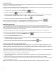
2. Select User Configured. 3. Enter an IP address. For simplicity, make the last segment of the IP one number different than the IP address of the console. Upon initial setup ONLY, the numbers used in the figure may be used to configure the TCP/IP settings of your PC. 4. Leave all other information blank and click OK. Note: The consoles default IP address is 192.168.168.168.
2. Enter an IP address. For simplicity, make the last segment of the IP one number different than the IP address of the console. Upon initial setup ONLY, the numbers used in the figure may be used to configure the TCP/IP settings of your PC. 3. Leave the DNS information blank. Note: The consoles default IP address is 192.168.168.168. If the PC is normally configured to Use the following IP address, ensure that all display information is recorded and kept prior to making any changes.
3. Select Connect Directly to Another Computer. 4. Select Guest. 5. Enter a name under Computer Name (it can be the site name). 12 6. Select the communication port to be used from the Select a Device dropdown list. 7. Select My use only. 8. For convenience, a shortcut may be created on your desktop. Click Finish to complete the wizard.
9. In the Network Connections window, right-click the new direct connection that was created and select Properties. 10. Under the General tab, select Configure. 11. Change the Maximum speed (bps) to 57600. 12. Disable all of the Hardware Features and click OK. 13. Select the Options tab. 14. Disable all of the Dialing Options.
15. Leave the existing Redialing Options as they are. 18. Select the Networking tab. 19. In the Type of dial-up server I am calling, select PPP: Windows 95/98/NT4/2000, Internet from the dropdown list then click OK. 16. Select the Security tab. 17. Select Advanced (custom settings). Check Operation of Connection 1. As before, open Network Connections. 2. Right-Click the new direct connection and select Connect. The status should change to connected.
Initial Console Configuration Before the console can be used, an intial setup must first be performed. This portion of the guide will instruct you on how to set custom parameters by navigating through the programming options and set up the TS-5 series console for the first time. Console Build Characteristics Each console is custom ordered and built to customer specifications. That means that all of the hardware (modules) and software options needed for your site are installed and tested.
Translation Options Language English Spanish (Español) Russian (Русский) Chinese (Simplified) (中文(简) Symbol MM M MMM Date/Time Options Short date format MM/dd/yyyy M/d/yyyy M/d/yy MM/d/yy MM/dd/yy Yy/MM/dd yyyy-MM-dd dd-MMM-yy User Defined Long date format EEEE, MMMM dd, yyyy MMMM dd, yyyy EEEE dd MMMM, yyyy dd MMMM, yyyy User Defined Year/month date format MMMM, yyyy User Defined Short time format HH:mm H:mm hh:mm a h:mm a Long time format HH:mm:ss H:mm:ss hh:mm:ss a h:mm:ss a User defined
Other Refresh Rate Show XML Tool Units Options Volume Liters Gallons Imperial Gallons Length Millimeters Centimeters Meters Inches Temperature Centigrade Fahrenheit Flow Liters/Hour Cubic Centimeters/Second Cubic Feet/Hour Gallons/Minute Gallons/Hour FMS - Line Pressure Pascal Bar Pounds per square inch Inches of Water Inches of Mercury Options How often the systems information is updated. Displays the Tool in the upper right corner of the browser window.
Date/Time Set To set the date and time, press the button that corresponds with your selection and select the correct option from the list. If your choice does not appear on the first screen, use the up and down navigation buttons to scroll through more options. When finished, confirm your selection by pressing the checkmark or OK button. It is important to enter the date and time information correctly to ensure reports and alarms can be accurately tracked.
Programming and Navigation Console Navigation The operating system is designed so that a user may navigate with ease. Manageable applications allow the user to modify programming options by responding to on-screen commands. The following instructions will give you a good feel for the operating system functions, so that issues can be corrected efficiently without interrupting dispensing or sales.
Character Navigation Buttons When prompted to enter system information, press the corresponding keys. Character Selection: Selects between upper case letters, lower case letters and numerals. Note how the characters on the input buttons change as you scroll through the options. Backspace: This will move the cursor one space to the left and delete the last character. Clear: Deletes all of the data on the entry line. Enter: Allows the data to be accepted.
System ID Group Name System ID Parameter Name Site Name Web UI URL ID Line 1 ID Line 2 ID Line 3 ID Line 4 ID Line 5 Parameter Value (Site Name) (http://localhost/tsa) (blank) (blank) (blank) (blank) (blank) System Configuration Group Name System Configuration Modules Expected Diagnostics Parameter Name Technical Support Key Enable Diagnostics DC Input (for future use) AC Input Relay Probe 2-Wire Sensor 3-Wire Sensor 4-20mA Input Printer Modem LON DIM Description Physical name of site.
Programming Modules The Fuel Management System is composed of a custom set of modules. Each module maintains individual characteristics. Parameters must be set to match the site configuration. The programming table below will assist in this setup.
AC Input Modules Group Name AC Input Modules Module # Channel # Parameter Value Parameter Name Number Gasoline Hooks per Dispenser Channels Name (2) (0) (AC Input 1) Enabled Active High (Yes) (Yes) Description Including diesel. Number of channels in use per module. Given name of channel. Yes if channel is used. Yes will activate channel when high voltage is present. No will activate channel with no voltage present.
Relay Modules Group Name Parameter Name Parameter Value Description Max Value Relay Modules Module # Channel # Input # 24 Channels (0) Number of channels in use per module. Name (Relay 1) Given name of the channel. abc# Enabled (Yes) Yes if the channel is in use. Yes/No Type (Unknown) Equipment connected to the relays output. Polarity (Normal) Allows the polarity to be inverted.
Programming FMS Parameters Here is where specific equipment parameters will be modified to match the site setup.
Manifold Tank System Group Name Parameter Name Fuel Management System Tanks Parameter Value Number of Tanks Name Type Manifolded Manifold # Tank # (0) (Tank 1) Special 1 (No) (1) Description Max Value Number of tanks in fuel system. Given name of the tank. Type of tank used. Enable a manifold. Number of manifold. 0-48 abc# Std/Spcl Yes/No 1-24 Manifolds Name Product # Delivery Threshold Theft Threshold Manifold # (Manifold 1) (1) (200.0 gal) (5.0 gal) Given name of manifold.
Tank Sentinel Anyware (TSA) Navigating Applications Remotely TSA offers several ways to navigate through applications: easy-to-read web pages that use hyperlink text (words or characters that, when clicked, take you to another page) to move through the menus, text and drop boxes and buttons allow inputs to be made efficiently, and on-screen prompts automatically pop-up instructions to verify each step.
Backup Configuration Files Download Backup configurations allow you to download the setup file and store it on any PC or Laptop connected to the console. This file is can be uploaded to the console in the future to recover lost settings or copy settings from one site to another. 1. Open a web browsing application, type the IP address (the default IP address is 192.168.168.168) into the address bar of the browser window. 2.
4. To download a site configuration, click Download. A File Download dialog box may appear, and, if it does, select Save to open an explorer window. 5. Select a location to save the configuration file. Then, type the File Name you want to create. Use something that identifies the file with the site and represents the date saved. Click Save. The file is now stored in the location of your choice and ready to upload when necessary.
2. Left-click once on Setup. 3. To upload a configuration file, click Upload on the Setup page. At this point, the console may prompt for a password if the proper access level has not been obtained. 5. An Upload Confirmation window will open. Left-Click Browse to locate the correct file. Find the location of your configuration file, click on the file name, and then click Open. 30 This process may take a few moments for the console to apply the settings and reboot.
Miscellaneous Leak Testing All TS-5 series console models meet (or exceed) the requirements of the U.S. Environment Protection Agency (EPA/530/ UST-90/006 test protocol) for Automatic Tank Gauging Systems (ATGS) for Monthly Monitoring for 0.2 gal/hr leaks of Underground Storage Tanks. The system(s) also meet (or exceed) the requirements for Annual Tank Tightness Testing for 0.1 gal/hr leaks of the National Work Group on Leak Detection Evaluations (NWGLDE).
Manually Forcing Static Leak Tests 1. To force a Static Tank Leak test, press the FMS button in the Application Window. 2. Press the Application Menu button. 4. The FMS Control Menu will display the systems available for testing. To view control options for the tanks system, press the Tanks button. 5. On the FMS Tank Control Screen, press the button that corresponds with the tank to be tested. 3. Select the Control button in the FMS Menu. 6.
Tank Leak Test Results Leak test results are either increase, passed, failed, or indeterminate. Reasons Why Tank Leak Tests Fail • The tank leaks. • Temperature instability – temperature variations of the product within the tank after a delivery is the most common source of interference and failed leak tests / false alarms (a failure to detect real leaks can also result). Look at the hourly temperature data on the leak test report and retest if the variation is more than a few tenths of a degree.
Reasons Why SCALD Tank Tests may Fail • Temperature • If a site is receiving deliveries frequently and the temperature of the fuel being delivered is several degrees different then the fuel in the tank, then SCALD will not be able to collect QIs due to thermal instability. The temperature of the fuel can not change more than .01°F during a 20 min QI. • If a pump control relay is stuck closed and the pump is running all of the time, the temperature in the tank can be much higher than the other tanks.
Manually Forcing Line Leak Tests Lines MUST be calibrated and enabled prior to forcing leak tests. 1. To force a Line Leak test, press the FMS button in the Application Window. 2. Press the Application Menu button. 4. The FMS Control Menu will display the systems available for testing. To view control options for the tanks system, press the Lines button. 5. On the FMS Line Control Screen, press the button that corresponds with the tank to be tested. 3. Select the Control button in the FMS Menu. 6.
Line Leak Test Results Line Leak test results are either increase, passed, failed, or indeterminate. Reasons Why Line Leak Tests Fail • The tank leaks. • Temperature instability – temperature variations of the product within the line is the most common source of interference and failed leak tests / false alarms (a failure to detect real leaks can also result). Look at the hourly temperature data on the leak test report and retest if the variation is more than a few tenths of a degree.
List of Alarms and Troubleshooting For all alarms conditions, the troubleshooting steps provided in this chapter are suggested actions to take in the event of an alarm. Follow all site policy procedures set by local governing agencies in the case of a spill, leak, or malfunction. If the steps provided by this manual or the site policy are followed and the system still requires additional support, contact Franklin Fueling Systems Technical Services.
Displayed Alarm / Warning 38 Device Description Dispensing Test Failed Line Extended Hook Signal Dispenser When pump is turned on, a pressure test is started. After specified time line pressure must be at least 12 psi. Also, if test is started manually an alarm and shutdown will occur if pressure during dispensing drops to 7.5 psi or below. Hook signal applied for an extended period of time.
Displayed Alarm / Warning Low battery Low low product volume Low product volume Manifold Gross Leak Detected Device Description Tank Backup battery is low. Tank/Manifold Product volume below Low Low limit set. The tank or manifold specified may be close to empty. Tank/Manifold Product volume below Low limit set. The tank or manifold specified may be close to empty.
Displayed Alarm / Warning 40 Device Probe Module Setup Error None Probe synchronization error Tank Product volume error Tank Program Error Detected Pump Request Ignored Relay Module is Offline Line Line Slot Relay Module Setup Error None RTD table error Tank SN2 Fuse Blown Slot SN2 Sensor On ChannelSN2 SN3 Data Error ChannelSN3 SN3 Dry Well SN3 Fuse Blown ChannelSN3 Slot SN3 High Brine ChannelSN3 SN3 ID Error ChannelSN3 SN3 Low Brine ChannelSN3 SN3 No Signal ChannelSN3 SN3 Pro
Displayed Alarm / Warning Device Description SN3 Sump Full ChannelSN3 3-wire sensor detected sump full of liquid. SN3 Sync Error ChannelSN3 SN3 Vapor ChannelSN3 SN3 Water ChannelSN3 Sudden Pressure Loss Line System Bus Error None System memory error System Setup Error Tank None Tank Gross Leak Detected Tank Tank Leak Detected Tank 3-wire sensor data signals not in sync with module. 3-wire discriminate sensor detecting vapors at location.
Appendix A - Standard Tanks Table Legend O/C = Owens Corning / FC Fluid Containment D = Diameter (Dia.
Type # Manufacturer Model Capacity (Gallons) Dimensions D x L (inches) S / DW Wall 27 Xerxes — 3,000 96 x 147 S 28 Xerxes — 4,000 75 x 263 S 29 Xerxes — 4,000 96 x 180 S 30 Xerxes — 4,000 76 x 252 D 31 Xerxes — 6,000 75 x 353 S 32 Xerxes — 6,000 6,000 96 x 246 97 x 251 S D 33 Xerxes — — 8,000 8,000 96 x 312 97 x 317 S D 34 Xerxes — — 10,000 10,000 96 x 378 97 x 383 S D 35 Xerxes — — 10,000 10,000 124 x 257 125 x 262 S D 36 Xerxes — — 12,000 12,0
Appendix B - Standard Products Table Product Name API Gravity (6B Compensation) Leaded Regular 63.5 Unleaded Regular 63.5 Unleaded Plus 62.8 Unleaded Extra 62.8 Unleaded Super 51.3 Diesel 32.8 Kerosene 41.8 #2 Fuel Oil 32.8 Appendix C - Typical Tank Leak Test Times For 7 Tank Sizes at Half Capacity ( Worst Case is 50% Full ) Tank Size in Gallons Typical - Tank Leak Test Times (to Finish) 4,000 2.0 hours 6,000 3.0 hours 8,000 4.0 hours 10,000 5.0 hours 12,000 6.