
Operators Guide User guide

5
Optional Modules
2-Wire Sensor Module Provides 12 inputs for 2-wire Standard sensors.
3-Wire Sensor Module Provides 8 inputs and supports both 3-wire and 2-wire sensors.
4-20 mA Input Module Provides 8 inputs that can be used for TS-LS500 line leak detection transducers.
4-20 mA EXP Explosion-proof module. Otherwise the same as the 4-20 mA Input Module.
AC Input Module Provides 12 inputs for dispenser hook signals, which are also required for LLD. This module
replaces external DHI boxes.
Probe Module Provides 12 inputs (8 in the TS-608) for LL2 probes.
Relay Module Provides 8 relay outputs (2-Amp) which are typically used to control the submersible pump
relays to provide pump or dispenser shutdown when line leak detection or other applications
are used. Not used in combination with TPI.
10-Amp Relay Module Provides 6 relay outputs which are typically used to control the submersible pump relays to
provide pump or dispenser positive shutdown upon alarm conditions.
Input / Output Module Provides 8 AC or DC voltage inputs that can range from 3 to 240 volts. Typically used for
vapor processors and generic devices, but not for dispenser hook signals. In addition, this
module also includes four 4-20 mA signal outputs which are typically used to interface to
an external device, such as a SCADA (Supervisory Control and Data Acquisition), building
monitoring system or fuel level monitoring.
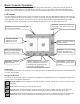
User Interface
LED Indicators – Three LEDs on the left side of the front panel give an “at-a-glance” indication of the system status. These
LEDs are standard on all systems. The green Power LED indicates that the system power is on. The yellow Warning LED
gives indication that the console has detected a malfunction or condition that has been deemed a Warning. The red Alarm
LED indicates that the system has detected an alarm condition.
LCD Touch Screen – The optional LCD touch screen (standard on the TS-5 (TS-608)) is the most commonly used user
interface for the Fuel Management System. This bright display allows easy viewing in any lighting condition. Touching
certain buttons or segments of the screen will allow access to menus or more detailed information. Do not use sharp or
pointed objects to operate the touch screen or damage may result. A “Sleep Mode” screensaver can be activated under
Preferences to automatically turn off the back light after 5 minutes to extend the life of the display. If improper operation
of the touch screen is noted, it may be necessary to calibrate the touch screen. Please refer to the Routine Maintenance
chapter of this manual for calibration procedures.
Alarms and Warnings
Alarms and warnings are designed to alert you with specic details when a problem occurs so that you can take appropri-
ate corrective action. System hardware failure warnings, tank related alarms, leak detection sensor alarms, and line leak
alarms will always notify the user in certain ways, other notication options are programmable.
Alarms and Warnings will always:
• Cause the red Alarm light or yellow Warning light to ash (standard).
• Change the alarm button from to .
Optionally they may:
• Sound the console’s internal alarm horn.
• Activate relay outputs and sound external alarm devices.
• Print alarm reports.
• E-mail alarm reports to a specied destination.
• Notify remote monitoring software via optional internal modem or Ethernet.
For help with troubleshooting alarms, refer to the Troubleshooting chapter of the T5 Series Programming
Manual (000-2142).