
Operators Guide Manual


34
FMS
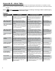
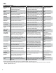
Sensor Alarms
Displayed Alarm Description Recommended Actions Reference Source
SN2 Fuse Blown The fuse on the channel of the 2-Wire
Sensor Module listed with the alarm is
blown.
Replace the 2-Wire Sensor Module*****
or use another channel on the module
for that sensor.
Applicable Service
Bulletins* / Sensors Setup in
Programming Manual
SN2 Sensor On The 2-Wire Sensor listed with the
alarm is in alarm position.
Check wiring, sensor operation and
location conditions.
Applicable Equipment
Guides**
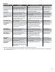
SN3 Dry Well The Monitoring Well Sensor listed with
the alarm is not sensing water in the
monitoring well.
Verify that there is no water in the
monitoring well. This condition may be
normal if no ground water exists.
Applicable Equipment
Guides**
SN3 Fuse Blown The fuse on the channel of the 3-Wire
Sensor Module listed with the alarm is
blown.
Replace the 2-Wire Sensor Module*****
or use another channel on the module
for that sensor.
Applicable Service
Bulletins* / Sensors Setup in
Programming Manual
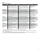
SN3 Sensor On The 3-Wire Sensor listed with the
alarm is in alarm position.
Check wiring, sensor operation and
location conditions.
Applicable Equipment
Guides**
SN3 Sync Error A communications error has occurred
between the console and the 3-Wire
Sensor listed with the alarm.
Check wiring, sensor operation and
location conditions. Attempt to re-
congure sensors with the ‘Congure’
button in Sensors > Control.
Sensors Setup in
Programming Manual /
Applicable Equipment
Guides**
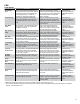
SN3 No Signal A communications error has occurred
between the console and the 3-Wire
Sensor listed with the alarm.
Check wiring, sensor operation and
location conditions. Attempt to re-
congure sensors with the ‘Congure’
button in Sensors > Control.
Sensors Setup in
Programming Manual /
Applicable Equipment
Guides**
SN3 ID Error The 3-Wire Sensor listed with the alarm
has been programmed incorrectly.
Verify that the 3-Wire Sensor is
programmed to match the type of
sensor.
Sensors Setup in the
Programming Manual /
Applicable Equipment
Guides**
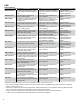
SN3 Data Error A communications error has occurred
between the console and the 3-Wire
Sensor listed with the alarm.
Check wiring, sensor operation and
location conditions.
Applicable Equipment
Guides**
SN3 Pwr Short The power wires of the 3-Wire Sensor
listed with the alarm have shorted.
Check wiring, sensor operation and
location conditions.
Applicable Equipment
Guides**
SN3 High Brine The 3-Wire Sensor listed with the alarm
is indicating a High Brine solution level
near the sensor.
Check wiring, sensor operation and
location conditions.
Applicable Equipment
Guides**
SN3 Low Brine The 3-Wire Sensor listed with the
alarm is indicating that a Low Brine
solution near the sensor.
Check wiring, sensor operation and
location conditions.
Applicable Equipment
Guides**
SN3 Product The 3-Wire Sensor listed with the alarm
is indicating that product is present
near the sensor.
Check wiring, sensor operation and
location conditions.
Applicable Equipment
Guides**
SN3 Sump Full The 3-Wire Sensor listed with the
alarm is indicating that the sump near
the sensor is full of a liquid.
Check wiring, sensor operation and
location conditions.
Applicable Equipment
Guides**
SN3 Vapor The 3-Wire Sensor listed with the
alarm is indicating that vapor is present
near the sensor.
Check wiring, sensor operation and
location conditions.
Applicable Equipment
Guides**
SN3 Water The 3-Wire Sensor listed with the
alarm is indicating that water is present
near the sensor.
Check wiring, sensor operation and
location conditions.
Applicable Equipment
Guides**
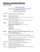
* Bulletins and Equipment Guides can be found on INCON’s website - http://www.incon.com
** The T5 Series Installation Guide (p/n 000-2150) and the T5 Series Programming Manual (000-2142) can be found on INCON’s
website - http://www.incon.com
*** If the tank is not listed as a standard tank in Appendix A: Standard Tanks Table (in the T5 Series Programming Manual (p/n 000-
2142), use the tank chart from the manufacturer to create a custom correction table.
**** Only use the product manufacturer’s specications sheet to accurately set volume correction parameters.
***** Fuses on Sensor Modules are NOT eld replaceable; the module must be replaced.