
Operators Guide Manual


29
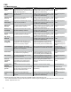
System
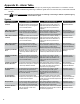
Displayed Warning Description Recommended Actions Reference Source
IS Barrier Violation The system has received an indication
that there is a Non-Intrinsically Safe
module installed in the IS area or that
the IS barrier has been removed.
Visually verify that all modules are
installed on the correct side of the IS
Barrier.
Installation Guide** /
Applicable Bulletins*
Low Battery Backup Battery should be replaced. Replace the backup battery with an exact
replacement from INCON.
Installation Guide** /
Applicable Bulletins*
Modem Error The number of expected Modem
Modules does not equal the number of
Modem Modules installed.
Verify the physical number of Modem
Modules installed and compare with the
number of Modem ‘Modules Expected’ in
the programming.
General Setup in
Programming Manual**
/ Applicable Bulletins*
Power Supply Module
is Ofine
This warning is only possible if there
is a TS-EXPC expansion console
connected. Failure to recognize the
expansion console’s PSM.
Cycle power to the console. Visually verify
that the green ‘RUN’ light on the module
is on continuously after the system boot is
complete.
Installation Guide** /
Applicable Bulletins*
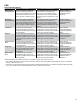
Printer Paper Jam Paper feed error. Paper or debris is
stuck in the printer.
Visually inspect the printer for the
problem. Correctly route the paper through
the printer to clear this warning.
Installation Guide** /
Applicable Bulletins*
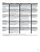
Probe Module
is Ofine
The specied Probe Module listed with
the alarm has experienced a problem
or may not be recognized by the
Controller Module.
Cycle power to the console. Visually
verify that the green ‘RUN’ light on
the applicable Probe Module is on
continuously after the system boot is
complete.
Installation Guide** /
Applicable Bulletins*
Probe Module
Number Mismatch
The number of expected Probe
Modules does not equal the number of
Probe Modules installed.
Verify the physical number of Probe
Modules installed and compare with the
number of Probe ‘Modules Expected’ in
the programming.
General Setup in
Programming Manual**
/ Applicable Bulletins*
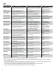
Relay Module
Number Mismatch
The number of expected Relay
Modules does not equal the number of
Relay Modules installed.
Cycle power to the console. Visually
verify that the green ‘RUN’ light on
the applicable Relay Module is on
continuously after the system boot is
complete.
Installation Guide** /
Applicable Bulletins*
Relay Module
is Ofine
The specied Relay Module listed with
the alarm has experienced a problem
or may not be recognized by the
Controller Module.
Verify the physical number of Relay
Modules installed and compare with the
number of Relay ‘Modules Expected’ in
the programming.
General Setup in
Programming Manual**
/ Applicable Bulletins*
Relay Module
Setup Error
This alarm is an indication that all
channels have been enabled. With all
six (6) 2A relay channels in use, 10A
channels seven (7) and eight (8) may
not be enabled.
Verify Relay Module programming. Module Setup in
Programming Manual**
* Bulletins and Equipment Guides can be found on INCON’s web site - http://www.incon.com
** The T5 Series Installation Guide (p/n 000-2150) and the T5 Series Programming Manual (000-2142) can be found on INCON’s web
site - http://www.incon.com