
Installation Guide User Manual

13
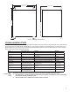
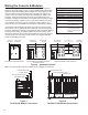
Non-Intrinsically Safe Module Wiring
Always lock out and tag electrical circuit breakers while installing or servicing this equipment
and any related equipment. A potentially lethal electrical shock hazard and the possibility of an
explosion or re from a spark can result if the electrical circuit breakers are accidentally turned on
during installation or servicing.
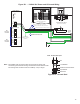
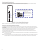
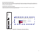
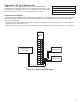
Important: Non-intrinsically safe wiring cannot be run in the same conduit as intrinsically safe wiring. Conduit
knockouts for IS and non-IS module wiring are clearly identied in Figure 7 for your reference. Non-
IS modules can be identied by their red faceplates and should always be installed to the left of the
moveable isolation barrier.
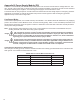
Appendix A: Controller Module (CM)
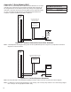
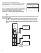
The Controller Module (CM) is a non-intrinsically safe module that acts like the brain of your console. The CM handles
all of the communication between the modules and then sends that information to your output devices. You can use the
optional touch screen LCD or external printer (depending on model and conguration) as output devices to communicate
with your system. The CM links to the status lights on the front of the console and the LCD via a exible cable connector.
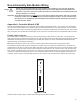
Flexible Cable Connector
The exible cable is installed at the factory and is just long enough to allow the door to fully open. It is protected from
high power wiring by the metal shroud attached to the CM. The cable should not be deformed, but should rather be freely
folded back into the shroud so that it does not get pinched when the door is closed. If the exible cable does become
detached though, it can easily be reattached.
Note: Make sure that the power to the console is turned off when disconnecting and reconnecting the cable.
To reattach the exible cable connector, identify the two sides of each end: there are metal bands on one side and no
metals bands on the other. It hooks into the CM by inserting one end of the ribbon into the LCD connector with it’s metal
bands facing to the left so that a metal-to-metal connection is made with the LCD connector’s pins. After the ribbon has
been correctly inserted all of the way into the LCD connector so that the metals bands are no longer showing above the
connection, it should hold itself rmly in place. Once the exible cable connector is properly attached to the CM’s LCD
connector, hook it up to the corresponding connector on the inside of your console’s door by making the same kind of
metal-to-metal connection that you made while inserting it into the CM’s faceplate.
Danger
Controller
Module
RUN
ERR
CONTRAST
MODEM
TXD
DTR
RXD
DCD
LCD/PRINTER
RX
LNK
ETHERNET
Figure A-1 – CM