
Installation Guide User guide

23
Danger
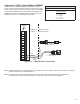
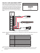
Intrinsically Safe Module Wiring
Always lock out and tag electrical circuit breakers while installing or servicing this equipment
and any related equipment. A potentially lethal electrical shock hazard and the possibility of an
explosion or re from a spark can result if the electrical circuit breakers are accidentally turned on
during installation or servicing.
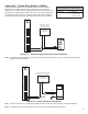
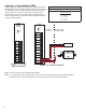
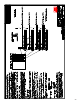
Important: Intrinsically safe wiring cannot be run in the same conduit as non-intrinsically safe wiring. Conduit
knockouts for IS and non-IS module wiring are clearly identied in Figure 6 on page 10 for your
reference. IS modules can be identied by their blue faceplates and should always be installed to the
right of the moveable isolation barrier.
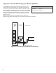
If local codes do not require the use of conduit, cable glands must be used at all enclosure knock-outs.
Gaps larger than 0.06 inch (1.5 mm) will violate safety approvals. Be certain to provide adequate IS
and non-IS wire separation.
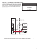
The IS modules in the T5 series consoles were certied as associated apparatuses using the “Entity Concept.” Under
this concept, the IS apparatus (eld device) has assigned parameters which, when properly matched to those of an
associated apparatus, will constitute an intrinsically safe system. If there are none available however, values of 60 pF / foot
(200 pF / m) for capacitance per wire pair and 0.2 uH / foot (0.7 uH / m) for inductance may be used. Refer to the associated
apparatus’s control drawing for acceptable cable run length calculations.
The 3WSNS has also been evaluated using the “System Concept” for the specic sensors indicated on the control
drawing 000-1722. When these sensors are used, cable must be limited to 1500 feet.
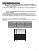
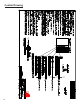
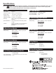
Associated apparatus parameter types and how they can be compared to IS apparatus parameter values are shown in
the table below.
Parameter Associated Apparatus Comparison IS Device
Maximum Voltage Uo < Ui
Maximum Current Io < li
Maximum Power Po < Pi
Total unprotected capacitance Co > Ci + Cc
Total unprotected inductance Lo > Li + Lc
Standard Terms
Term Denition
Uo Maximum Output Voltage
Ui Maximum Input Voltage
Io Maximum Output Current
Ii Maximum Input Current
Po Maximum Output Power
Pi Maximum Input Power
Co Maximum External Capacitance
Ci Maximum Internal Capacitance
Cc Cable Capacitance
Lo Maximum External Inductance
Li Maximum Internal Inductance
Lc Cable Inductance