
Installation Guide User guide
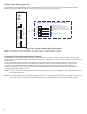

12
Wiring the Console & Modules
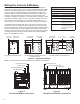
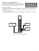
Conduit must only enter the console enclosure through the designated
knockouts as shown below in Figure 6. When installing additional modules,
INCON recommends installing non-IS modules from left to right (from the
open slot closest to the power supply) and IS modules from right to left.
In this scenario, all unused slots will be concentrated in the middle of the
enclosure, which lets the IS barrier be easily moved and allows for the
possibility of adding future modules to the system without needing to rewire
those devices already in place. It’s also a good idea to always start wiring
your module at the bottom-most set of channels (usually Channel 1) to
further future-proof your installation and avoid any unnecessary confusion.
It is important that intrinsically safe wiring only enter the console through
IS knockouts, and non-intrinsically safe conduit only enter through non-IS
knockouts. Maintain the integrity of the intrinsically safe modules by keeping
probe and sensor wiring in conduit separate from all other wiring. Probe
and sensor wiring may be run in the same conduit as long as they are both
receiving power from the same console and the wire complies with NEC
504.30 or applicable local codes.
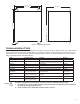
Console Specications
Line Voltage: 115/230 V~ +15%, -10%
Frequency & Power: 50/60 Hz, 150 W maximum
Storage Temp.: -20° to 60° C (-4° to 140° F)
Operating Temp.: 0° to 40° C (32° to 104° F)
Operating Humidity: 0 to 95%, non-condensing
Cleaning: Cloth or sponge slightly
dampened in mild detergent
Splash Resistance: Not to be exposed to direct
spray, splash or drips
Location: Indoors in an ofce or in a
non-hazardous pollution
degree 2 environment per
IEC60664
TS-5000/TS-EXPC Conduit Knockouts
(bottom view)
Intrinsically
Safe Knockouts
Non-Intrinsically
Safe Knockouts
IS or non-IS depending on
placement of moveable barrier
TS-550/TS550evo/TS-EMS/ TS-EXPC2
Conduit Knockouts
(bottom view)
Intrinsically Safe
Knockouts
Non-Intrinsically
Safe Knockouts
TS-5/TS-608 Conduit Knockouts
(side view)
Non-Intrinsically
Safe Knockout
Intrinsically
Safe Knockout
Figure 6 – Conduit Knockouts
Note: No communication ports are available on the TS-EXPC or TS-EXPC2.
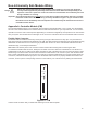
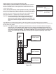
Figure 8
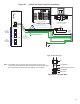
TS-5000/TS-550 Module Connections
Non-IS
Modules (red)
Controller Module (CM)
Power Supply Module (PS)
Isolation Barrier
IS Modules (blue)
TS-5000 (front view with cover removed)
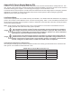
Figure 7
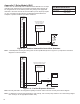
TS-5/TS-608 Module Connections
Controller Module (CM)
Power Supply Module (PS)
Probe Module (PRB)
TS-5 (front view with cover removed)
Isolation Barrier