
Installation Owner manual


3
Setup
Setup can be performed using either a local user interface (LCD on the console) or a web interface (remotely connecting
with Tank Sentinel Anyware). In both of these cases, the sequence is the same. Refer to Chapter 6 - Level Probe
Installation in the Automatic Tank Gauge/Leak Detection System Installation Guide (p/n 000-1050) for complete probe
setup information.
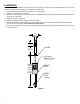
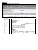
Under 1. FMS>Tanks>TankN>Probe select Float Type
as Gas Density or Diesel Density. See Figure 2.
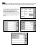
Enter the Density Calibration constant. This value can 2.
be obtained directly from the oat that is being installed;
refer to the Density Calibration eld in Figure 4.
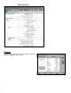
Under 3. FMS>Tank>TankN>Limits, two new
parameters should appear: “High Density Limit” and
“Low Density Limit”. These limits will be set to the default
range limit, this limit can only be decreased to narrow the
expected density. The ATG will generate an alarm when
the density measurement is outside of this range. See
Figure 5.
Figure2
Figure3 Figure4
Figure5