
Installation Owner manual


2
Installation
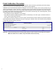
The selection and the installation of the probe is exactly the same as in cases of regular level measurement. The only dif-
ference is in the number and sequence of the oats. To install oats:
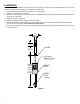
Remove the E-ring and washer from the bottom of the probe shaft.1.
Install the 3" product oat on the shaft.2.
Slide the 4" density oat on to the probe shaft with the cylindrical cavity facing the product oat and the metal ballast 3.
facing the tip of the probe.
Install the water oat if required.4.
Replace the washer and E-ring that you removed in Step 1.5.
Record the calibration constant marked on the bottom of the product and density oats. Make sure that both oats 6.
have the same constant. Donotmixoatsfromdifferentkits!
Carefully move the oats to the bottom of the probe shaft to prevent damage. The product oat should now be inside 7.
of the density oat.
2.00"
(50.8 mm)
REF.
2.88"
(73.15 mm)
7.00"
(177.8 mm)
REF.
PROBE
SHAFT
LENGTH
=
MODEL
No. (IN
INCHES)
DENSITY
FLOAT
WATER
FLOAT
(optional)
3" (76.2 mm)
PRODUCT FLOAT
(CUTAWAY VIEW SHOWN)
SPACER
Figure1