
Installation Instruction Manual

©2007 FFS 000-0526 Rev. B
T5 Retrot LCD Display
Installation Instructions
Tools Required
• #1Phillipsscrewdriver
• X-actoknife(orequivalent)
• 3/16Nutdriver
Replacing an Existing LCD Display, TS-5 and TS550/5000
1. Powerdownthesystem.
2. Openthesystemdoor.
3. TS550/5000 models only,removetheshieldinstalled
onthebackofthedoor.
4. RemovetheoldLCDDisplay.Carefullydisconnect
cablesatJ2,J3andJ4.
5. Slidethewideribboncablethroughtheferritebeadthat
isalreadyinstalled,andconnecttoJ2.
6. T5 Only -Foldthewideribboncableoverasshownin
Figure1.
7. FittheLCDDisplayintotheopeningfromthedoor-
backandsecureusingthefour3/16inchstandoffs
(T550/5000)or#4-40screws(T5).
8. LocateJ3(Figure1)andgentlypullthetabopenby
graspingthesidesandpullingawayslightly.Insertthe
narrowribboncableintoJ3:Thesidewiththemetal
ngersshouldfaceyouandthebackingfaceawayfrom
you.Oncethecableisproperlyseatedgentlypushthe
tabbackintosecurethecable.
9. Plugthe2wirecableintoJ4(Figure1)sothatthe
centerkeyisfacingawayfromyou.
10. T550/5000 Only -Replacethemetalshield;making
surethatthegroundwireiscapturedbyoneofthe
mountingscrews.
Adding an LCD Display to the TS-550/5000
1. Powerdownthesystem.
2. Openthesystemdoor.
3. Removetheshieldinstalledonthebackofthedoor.
4. Removethefourscrewsandstandoffsthatsecurethe
LCDDisplayblank-offplatetothebackofthedoor.
5. RemovetheLCDDisplayblank-offplate(theblank-off
platemaysticktotheoverlay;gentlypryitoff).
6. Fromtheinsideoftheenclosure,useasharppointed
knifetocutasmall“X”intheoverlayatthefourcorners
oftheLCDDisplayenclosureopeninginthemetaldoor.
7. Useasharpknifetoremovetheportionoftheoverlay
coveringtheLCDDisplayopening.
8. FittheLCDDisplayintotheopeningfromthedoor-
backandsecureusingthefour3/16inchstandoffswith
lock-washers.
9. Slidethewideribboncablethroughtheferritebead
(Figure1)sothatthesideofthecablewiththemetal
ngersisfacingthesamedirectionasthedouble
sidedtapeontheferritebead.Positiontheferritebead
approximately1inchfromtheright-handcornerofthe
circuitboard.Thiswillallowfutureprinterinstallation.
10. PlugthewideribboncableintoplugJ2(seeFigure1)
ontheinterfacePCBsothatthesidewiththebackingis
facingyouandthesidewiththemetalngersisaway.
11. Removethetabfromthebackoftheferritebeadto
exposetheadhesiveandpushrmlyontothebackof
thedoorasshowninFigure1.
12. LocateJ3(Figure1)andgentlypullthewhitetabopen
bygraspingthesidesandpullingawayslightly.Insert
thenarrowribboncableintoJ3:Thesidewiththemetal
ngersshouldfaceyouandthebackingfaceaway
fromyou.Oncethecableisproperlyseated,gently
pushthetabbackintosecurethecable.
13. Plugthe2wirecableintoJ4(Figure1)sothatthe
centerkeyisfacingawayfromyou.
14. Replacethemetalshield;makingsurethattheground
wireiscapturedbyoneofthemountingscrews.
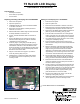
Figure 1. T5 Board Installation (TS-5 shown)
J2
J4
J3
Ferritebead
FerritebeadlocationforTS-550/5000