
Manual


3
1. Connect the right ground terminal to the earth
ground bus at the service panel. Use #14 AWG
copper conductor wire.
2. Connect the left ground terminal to the metal rigid
conduit used to feed service panel wiring with #14
AWG copper conductor wire.
3. Connect power wires to the appropriate terminals
on the power supply terminal strip: Ground, Line,
Neutral, Earth Ground.
Sensor Wiring
All sensor wiring is to be intrinsically
safe and run into the right side of
the wiring bay and be fully contained
within the intrinsically safe wiring
compartment. When replacing
the faceplate, make sure no wires
are pinched under the faceplate
compartment divider.
1. Remove the wire jumper from each contact input
that you plan to use.
2. Wire each normally closed sensor to the
appropriate terminals.
Note: Only the following INCON sensors can be used
with the S940 console:
• TSP-ULS Universal Liquid Sensor
• TSP-HLS High Level Sensor
• TSP-UHS Universal Hydrostatic Sensor
• TSP-HFS Horizontal Float Switch Sensor
Using other sensors will violate the warranty.
Note: Sensors must be 3rd party or simple apparatus.
Relay Wiring
1. Wire the device to the relay terminal strip in
accordance with the instructions furnished by the
manufacturer of the device.
2. Observe the relays for terminal layout and
voltage / current limits (10A @ 240 VAC).
Operation
When the contact input senses an open condition the
corresponding red alarm LED will light and the annunciator
will sound, and if a relay has been programmed it will
change states.
The annunciator can be silenced by pressing the
silence / test button. It will continue to sound until this
button is pressed, even if the actual alarm condition clears.
The alarm LED (and relay if programmed) will turn off
when the alarm condition clears.
If there is no alarm condition, and the alarm reset button
is pressed, the audible alarm will sound and the relays will
activate. Press again to silence and turn off the relays.
Programming
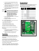
Relay Conguration
Choose which output relay will be triggered by each sensor
and activate them by moving the appropriate “Output
Relays” DIP switch to the “on” position. The DIP selector
switch is located in the wiring bay.
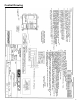
DIP
Switch
Relay Effect
1
1
Sensor 1
2 Sensor 2
3 Sensor 3
4 Sensor 4
5
2
Sensor 1
6 Sensor 2
7 Sensor 3
8 Sensor 4
9 1 Steady or Single Pulse Alarm
10 2 Steady or Single Pulse Alarm
Figure 3: DIP Switch Location
DIP Switches
Warning