S940 Sensor Alarm Console Installation and Operation Guide Franklin Fueling Systems • 3760 Marsh Rd. • Madison, WI 53718 USA Tel: +1 608 838 8786 • 800 225 9787 • Fax: +1 608 838 6433 • www.franklinfueling.
Notice INCON reserves the right to change this document and specifications at any time without notice. INCON makes no expressed or implied warranty with regard to the contents of this manual. INCON assumes no liability for errors or omissions, or for any damages, direct or consequential, that may result from the use of this document or the equipment that it describes.
Contents Important Safety Messages........................................................................................................ 1 Introduction.................................................................................................................................... 2 Product Description. .................................................................................................................... 2 Installation........................................................................
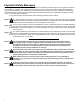
Important Safety Messages INCON equipment is designed to be installed in association with volatile hydrocarbon liquids such as gasoline and diesel fuel. Installing or working on this equipment means working in an environment in which these highly flammable liquids may be present. Working in such a hazardous environment presents a risk of severe injury or death if these instructions and standard industry practices are not followed.
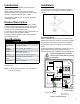
Introduction This manual contains installation instructions for the INCON S940 Alarm Console. Please carefully read this entire manual. Failure to follow the instructions in this manual may result in faulty operation, equipment damage, injury or death. Installation Mounting To mount the unit to the wall, first attach the included mounting tabs to the box (figure 1) and then attach it to the wall. This equipment should only be serviced by an INCONcertified technician.
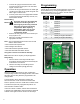
1. Connect the right ground terminal to the earth ground bus at the service panel. Use #14 AWG copper conductor wire. 2. Connect the left ground terminal to the metal rigid conduit used to feed service panel wiring with #14 AWG copper conductor wire. 3. Connect power wires to the appropriate terminals on the power supply terminal strip: Ground, Line, Neutral, Earth Ground.
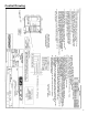
Control Drawing 4
©2009 FFS 000-2147 Rev.