LS500 Auto Learn Line Leak Detection Installation & User’s Guide Manual # 000-2145 Revision E date August 2012 Changes from Previous Revision Updated to Incude TS-550evo Franklin Fueling Systems • 3760 Marsh Rd. • Madison, WI 53718 USA Tel: +1 608 838 8786 • 800 225 9787 • Fax: +1 608 838 6433 • www.franklinfueling.
Notice Franklin Fueling Systems (FFS) strives to produce the finest manual possible and to ensure that the information that it contains is complete and accurate. However, FFS reserves the rights to change this document and specifications at any time without notice. FFS makes no expressed or implied warranty with regard to the contents of this manual.
Contents Notice................................................................................................................................2 Important Safety Messages.............................................................................................4 Overview...........................................................................................................................5 Site Requirements................................................................................................
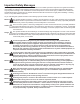
Important Safety Messages INCON equipment is designed to be installed in association with volatile hydrocarbon liquids such as gasoline and diesel fuel. Installing or working on this equipment means working in an environment in which these highly flammable liquids may be present. Working in such a hazardous environment presents a risk of severe injury or death if these instructions and standard industry practices are not followed.
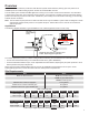
Overview The TS-LS500 is a continuous product line leak detection system that monitors the primary pipe. This product is an available option of Franklin Fueling Systems’ TS-550 and TS-5000 FMS consoles. The TS-LS500 system includes the FMS application running on a T5 series console and a transducer. One transducer is required per product line, which measures the line pressure. Line Pressure is created by the pump and static seating pressure is metered by a pressure relief valve.
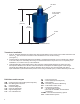
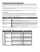
3/4" NPT 2-3/8" (70mm) across flats 6.25" (159 mm) 5.13" (130 mm) 2" NPT Figure 2: TS-LSU500 Dimensions Transducer Installation 1. Apply UL Classified Gasoline / Oil resistant pipe dope thread sealant to the threads of the LSU500 Transducer and use a 2 3/8” open-end wrench to install it in the Leak Detector Port of the STP housing (see Figure 1). 2. Install Couplings, threaded Rigid Metal Conduit (RMC), and Explosion / Weather Proof Junction Boxes (J-Boxes) in the STP sumps.
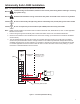
Intrinsically Safe LS500 Installation Note: The Intrinsically Safe 4-20mA Input Module has a BLUE face. Warning Lockout and tag circuit breakers, and disconnect console power wiring before installing or servicing any system wiring. Warning DO NOT make transducer wiring connections with power connected to the console or any module. Caution Do not run intrinsically safe (IS) wiring and non-intrinsically safe (non-IS) wiring in the same conduit.
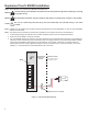
Explosion Proof LS500E Installation Note: The Explosion Proof 4-20mA Input Module has a RED face. Warning Lockout and tag circuit breakers, and disconnect console power wiring before installing or servicing any system wiring. Warning DO NOT make transducer wiring connections with power connected to the console or any module. Caution Do not run intrinsically safe (IS) wiring and non-intrinsically safe (non-IS) wiring in the same conduit.
LS-500 Setup (Console Programming) The following instructions are a guide to programming the LS-500 only. The administrator password will be necessary to save the programming changes. For instruction on FMS programming, or how to obtain the Administrator access level, please refer to the T5 Series FMS Programming Guide (p/n 000-2142) or the TS-550evo FMS Programming Guide (p/n 000-2173).
4-20mA Input Module TS-LSU500 Transducers use a single 4-20mA channel per product line which allows the console to monitor the pressure on each product line. Parameter Parameter Value Channels Select the number of channels used for LLD. Name Text box, name each channel to easily identify in the mapping. Enabled Select Yes. Service Type Select Line Leak Detector. This indicates that the type of device connected to the channel to indicate that the device is a TS-LSU500 transducer.
Relay Module The 2A relay module contains 8 separate relays, called relay channels. The 10A relay module contains 6 relay channels. Each relay is used by the console to turn a specific STP on or off in applications where Turbine Pump Interface (TPI) is not used.
Turbine Pump Interface (TPI) Applications In systems where TPI is used, the relays are not needed for line leak or STP operation. Communication with the FFS smart controllers is done exclusively by the RS-485 connection. Refer to the Programming Manual for full TPI instructions.
Fuel Management Systems (FMS) Line Application Set-Up Setting up the lines establishes which transducer and relay is used on the specific line and allows the user to change certain parameters in the operation of the line leak testing. Make sure the line is holding at or above the minimum required pressure (see page 5). If the pressure is too low, review the check-valve used, and adjust the pump / pump controller for proper pressure.
Line Status and Control Screens The status of each line channel can be viewed at any time by navigating to the Line Status or Control screens. To get to the Line Status or Control screens, go to FMS > Status > Lines or FMS > Control > Lines. LS500 Status Screen The status of each line can be viewed at any time by navigating to the line status or control screens.
LS500 Control Screen Status Section Indicator Description Line Pressure Indicates the current line pressure Enabled Green, enabled. Red, disabled Not Learned Red, if not learned. Gray, if learned Pump On Green, if the STP is on Alarm Red, if in alarm.
Pre-Operational LS500 Testing The line stability test procedure assumes that all STP’s, pump controllers, and AC inputs have been installed, wired, calibrated and are operational and in accordance with their respective installation and operation procedures. It also assumes that all T5 Series FMS console programming has been completed accurately. Caution DO NOT proceed to the Learn Process until each line successfully completes pre-operational testing.
Learn Process Each line must be learned before the FMS system can continuously monitor it. Learning involves bleeding the line pressure down to zero, with no air in the line, then introducing a calibrated leak, facilitated by the leak generating kit (TSALCAL). The system learns this pressure decay curve and uses it to compare test data during continuous operation to determine if there is a leak in the line. Note: All console programming must be completed prior to the learn process.
5. When finished, the message Learn Completed – No Errors is displayed on-screen and the Not Learned indicator will become inactive. Note: If any errors are encountered at any time during the Learn Process, the screen will display the applicable error message and the Not Learned indicator will remain active. Refer to the Alarms chapter of this guide for information on troubleshooting any errors that are displayed. 6. Once the line has been successfully learned, the line will automatically be enabled.
LS-500 Reports Line test reports are available on demand from the console or using the web page. The reports can also be generated by using the rules engine. Several report options are available to print or save generated reports. For more information on reports in general, please refer to either the T5 Series Programming Manual (p / n 000-2142) or the T5 Series Operator’s Guide (p / n 000-2151) or the TS-550evo FMS Programming Guide (p/n 000-2173).
LS-500 Alarms and Warnings Alarms During the Learn Process Alarm Symptom Failed to pressure up STP is not turning on Possible Cause Resolution Verify that the 4-20 transducer is a relay / TPI input Check the programming Is the pump controller powered on? Check the controller If controlled by a relay, is the Test the voltage on the relay common of the relay wired to 110 common Volts? Is another STP turning on? Check the other STPs Is the 4-20 transducer in alarm? Check alarms Is the wrong tr
Operating Alarms (Continued) Test Result Failed to catch pressure Sudden Pressure Loss Catastrophic leak Investigate for leaks Is the clamp valve down Look at the pressure gauge on the needle valve kit for operating pressure Condition Pressure was less that 12 psi after programmed delay when STP turned off Pressure dropped to less than 5 psi Possible Cause Resolution Check valve damaged Investigate, force a manual test and observe pressure Dispenser solenoid is still open after hook signal is o
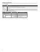
Test Result Alarms Test Result Condition Possible Cause Resolution Pass Line is tight Fail Actual Leak Line pressure variations are outside threshold Check for leaks, force leak test to verify Temperature Instability Temperature fluctuations cause pressure variances Check for leaks, force leak test to verify Inadequate learning Line not properly bled to zero during Re-learn the line, follow learning procedures Abort (no indication) STP Shutdown Air was not bled out of the line prior to lear
LS-500 Functional Testing Perform a Functional Test annually. This test will verify that the LS-500 application will detect and alarm on a leak condition. This test should be performed during times when there is no dispensing. 1. If the channel is Enabled, disable the channel. At the T5 Series FMS console (via LCD or by the web page), navigate to the FMS > Lines Control screen. Press the Enable / Disable button to disable the line. 2. Remove the plug in the needle valve kit on the manifold.
©2012 FFS 000-2145 Rev.