
User guide


3
Product Description
The DC400 system uses a sump sensor to detect the
presence of liquid in the STP (Submersible Turbine Pump)
or dispenser sump. If liquid is detected, the system will
shut down power to the STP or dispenser.
The DC400 system consists of the 404-4 Controller and
either a 2-Wire or 3-Wire sensor. Follow these instructions
for installation of the 404-4 Controller. Franklin Fueling
Systems sensors approved for use with the DC400 system
come with their own installation instructions.
Specications:
Input line voltage: 90 – 250VAC 50/60 Hz
404-4 power consumption: 2W
Relay switch conguration: SPST
Relay switch contact rating: 12A continuous, 250VAC
maximum
Operating temperature: -20 to 60 degrees C
Hazardous location
category:
Class I, Div 1, Group D
Refer to Franklin Fueling Systems control drawing 000-1737
Installation for Dispenser Cutoff
Notice! Only qualied service
technicians experienced with petroleum
dispensing and pumping systems
should install the DC400 system.
Notice! Do NOT exceed the 12A
(continuous), 250VAC relay contact
rating of this controller. Relay contacts
are not fused.
Note: Install this kit ONLY in a UL listed dispenser.
Note: If the is no junction box or open port on the junction
box, you cannot install this kit.
1. Shut off all power to the dispenser. Lock out and
tag the corresponding dispenser circuit breaker.
2. Open / remove the dispenser lower panel for
access to the dispenser hazardous area. Inspect
the hazardous area to locate the dispenser
explosion proof power entry junction box. The 404-
4 controller will be wired into the dispenser via a
spare conduit hub located on the dispenser power
entry junction box.
3. Determine where to best locate the 404-4
controller and how best to plumb conduit from
the dispenser spare conduit hub to the 404-4
controller. The 404-4 controller must be located
so that regular servicing of the dispenser (such as
changing of fuel lters) will not be impeded. The
404-4 controller can be located in the dispenser
hazardous area or suspended down below the
dispenser in the dispenser sump as room dictates.
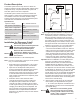
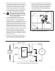
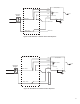
Refer to gure 1.
404-4
Controller
2-Wire or
3-Wire sensor
Dispenser
Junction Box
EYS
Dispenser
Sump
Cable Connection
Dispenser
Base
EYS
Figure 1: Typical System Installation in a Dispenser Sump
Note:
Because each dispenser installation is unique it is
impossible to provide a “one size ts all” conduit
tting kit. Necessary explosion-proof conduit and
conduit ttings must be determined and supplied by
the installer. The 404-4 controller conduit size is 3/4”
NPT. Simple ttings such as elbows, sweeps, unions,
and nipples should be used and must be UL listed and
suitable for use in Class I, Div 1, Group D locations.
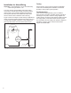
4. Open the dispenser power entry junction box
cover and retain hardware for later use. Remove
spare junction box plug and plumb explosion-proof
conduit from the spare conduit entry hub to the
404-4 controller power port (the port with 6 wires
protruding). Thread the 6 wires coming out of the
power port of the 404-4 controller through the
conduit to the dispenser power entry junction box.
Important! Be sure installation of conduit, ttings and
wiring is in accordance with local, State and
National electrical codes. A conduit seal must be
installed between the dispenser J-box and the
controller. The conduit seal must be within 18" of
the dispenser J-box and the 404-4 controller. Refer
to NEC NFPA 70, article 501.15 (A) (3), 2011. Make
sure the dispenser power entry junction box has
enough spare room to accommodate the additional
404-4 controller wires (see the table on page 2).
Important! When tightening the conduit to the 404-4
controller, use a wrench on the conduit ttings and
not the 404-4 controller body.
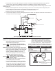
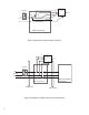
5. Wire the 404-4 power wiring per the schematic
that matches your dispenser listed in Figures
7 - 14. Contact your dispenser manufacturer for a
wiring diagram if you are unsure of the dispenser
input power wiring.
Make sure to connect both ground
wires and verify they are connected
to earth ground. Failure to do so may
result in a re or explosion hazard in
case of a fault condition.
Warning
Warning
Warning