DC400 Dispensing Cutoff System 404-4 Controller Installation Instructions Franklin Fueling Systems • 3760 Marsh Rd. • Madison, WI 53718 USA Tel: +1 608 838 8786 • 800 225 9787 • Fax: +1 608 838 6433 • www.franklinfueling.
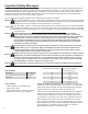
Important Safety Messages Franklin Fueling Systems (FFS) equipment is designed to be installed in association with volatile hydrocarbon liquids such as gasoline and diesel fuel. Installing or working on this equipment means working in an environment in which these highly flammable liquids may be present. Working in such a hazardous environment presents a risk of severe injury or death if these instructions and standard industry practices are not followed.
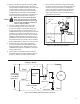
Product Description The DC400 system uses a sump sensor to detect the presence of liquid in the STP (Submersible Turbine Pump) or dispenser sump. If liquid is detected, the system will shut down power to the STP or dispenser. The DC400 system consists of the 404-4 Controller and either a 2-Wire or 3-Wire sensor. Follow these instructions for installation of the 404-4 Controller. Franklin Fueling Systems sensors approved for use with the DC400 system come with their own installation instructions.
6. Connect the sensor wire cable coming from the 404-4 controller to the appropriate Franklin Fueling Systems sensor. Refer to the sensor’s installation instructions for installation, wiring and testing of the sensor. The sensor must be installed in accordance with the sensor’s control drawing and with Franklin Fueling System’s control drawing 000-1737. 7. Double check all dispenser & controller power wiring to be sure it is correct then replace the dispenser power entry junction box cover.
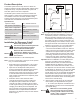
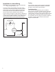
3. Remove the STP junction box cover / plug. Make sure the STP junction box has enough room to accommodate the additional 404-4 controller wires (see the table on page 2). Thread the six 4044 power wires from the power port through the conduit fittings and plumb the conduit fittings to the 404-4 controller. Connect the controller power wires to the STP wiring as shown in figure 4. Make sure to connect both ground Warning wires and verify they are connected to earth ground.
Installation for Alarm Wiring Testing Important! For all applications, do not exceed the relay contact rating of 250VAC, 12A. Test the function of the system according to applicable codes. Test immediately after installation, and at least annually to verify proper system operation. The relay contacts (Orange / Black and Orange wires) on the 404-4 controller are normally closed dry contacts (when power to the controller is applied) that will open when liquid is detected.
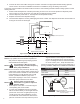
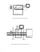
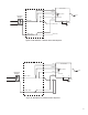
Dispenser-Specific Wiring 404-4 Controller ORG/BLK 12A, 240VAC ORG BLK Dispenser Breaker Sensor H WHT 120-240VAC N G 1 G GRN 2 GRN/YEL W-V 3 4 5 6 7 8 9 10 11 12 Main Junction Box Figure 7: 404-4 Wired to a 120V Dresser-Wayne Vista 3 Series Dispenser Junction Box 404-4 Controller BN V Y V W 12A, 240VAC W-R W-BN W-BK BK ORG/BLK ORG Sensor H 120-240VAC N G GRN BLK WHT G GRN/YEL Line N Dispenser Control Power Figure 8: 404-4 Wired to a Dresser Wayne Ovation Dispenser 7
404-4 Controller ORG/BLK Dispenser Breaker 12A, 240VAC ORG Line BLK H WHT N Sensor 120-240VAC G GRN G GRN/YEL Neutral Earth Ground Main Junction Box Figure 9: 404-4 Wired to a Gilbarco Eclipse Dispenser 404-4 Controller ORG/BLK 12A, 240VAC ORG BLK WHT Sensor H 120-240VAC N G GRN G GRN/YEL Dispenser Breaker Line Neutral Earth Ground BLK A-2 BLK WHT A-13 WHT GRN/YEL A-10 GRN/YEL Electronics Cabinet (CD Module) Main Junction Box Field Conduit Main Conduit Figure 1
Main Junction Box 404-4 Controller BLK ORG/BLK 12A, 240VAC Sensor ORG Dispenser Breaker WHT 120-240VAC BLK - ACH G G GRN BLK - ACH WHT - ACC GRN/YEL WHT - ACC Figure 11: 404-4 Wired to a Tokheim 262 or 262A Dispenser Dispenser Junction Box 404-4 Controller BLK ORG/BLK 12A, 240VAC Sensor ORG Dispenser Breaker WHT 120-240VAC UDC - ACH G GRN 9 UDC - ACC G GRN/YEL 10 Figure 12: 404-4 Wired to a Tokheim Premier Dispenser 9
Page intentionally blank 10
Page intentionally blank 11
©2011 000-0316 Rev A