
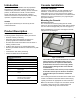
Installation Guide User Manual

2
Introduction
This manual contains installation and site preparation
instructions for FFS’s Colibri console. Safety issues,
troubleshooting information, warranty, service, and return
policies, as dened in this manual, must be followed.
Please read this entire manual carefully. Failure to
follow the instructions in this manual may result in faulty
operation, equipment damage, injury or death.
Installer
This equipment should only be serviced by an FFS-
certied technician.
Product Description
The Colibri is a complete, automatic, continuous
monitoring system that performs a variety of functions.
• Performs inventory monitoring
• Generates reports automatically in response to
preset / programmed conditions and alarms
• Provides audio-visual annunciation when an alarm or
warning condition exists
• Is able to print reports on an external USB printer.
• Remotely accessible via Ethernet or RS-232 to any web
browser.
• Leak detection and density monitoring
• Tank reconciliation and Autocalibration
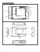
Console Installation
Console Location
Install the console indoors in an area classied as non-
hazardous. Locate the console where personnel can
easily make use of it; mount it at eye level for operator
convenience. Mount the console level on a vertical surface
between 2 feet (0.6 m) and 6 feet (1.9 m) high using the
appropriate fasteners.
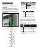
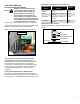
Mounting the Console
Removing the cover
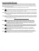
The cover must be removed by lifting with two hands.
Press in on the cover release tabs on both ends to release
the cover and lift it straight away from the unit (Figure 1).
When reinstalling the cover put it on straight so the LED
light pipes are not damaged.
Figure 1: Inside Cover
The Colibri console must be mounted in a location
where explosive or ammable vapors are not
present, otherwise an explosion hazard will be
created which can result in severe injury, death,
serious property damage and/or environmental
contamination.
Leave a minimum of two inches (5.1 cm) of space
around the console open to allow for ventilation,
communication port connections, conduit and
wiring.
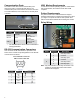
Two mounting screw holes are located on the inside of the
console. Use fasteners that have sufcient load carrying
capacity and which are appropriate for wall construction.
Make sure that there is enough room around the console
for conduit coming into the unit, communication port
connections, probe wiring, and console access.
Console Specications
Line Voltage:
110-240 V
~, 1.0 A
Frequency & Power: 50/60 Hz, 150 W maximum
Storage Temp.: -20° to 60° C (-4° to 140° F)
Operating Temp.: 0° to 40° C (32° to 104° F)
Operating Humidity: 0 to 95%, non-condensing
Cleaning: Cloth or sponge slightly dampened in
mild detergent
Splash Resistance: Not to be exposed to direct spray, splash
or drips
Location: Indoors in an ofce or in a non-
hazardous pollution degree 2
environment per IEC60664
Relay Rating 10A @ 240V~
LED Light Pipes
Cover Release Tabs