ATG Moormann Interface Installation Guide Franklin Fueling Systems • 3760 Marsh Rd. • Madison, WI 53718 USA Tel: +1 608 838 8786 • 800 225 9787 • Fax: +1 608 838 6433 • www.franklinfueling.
Contents Notice............................................................................................................................................... ii Important Safety Messages........................................................................................................ iii Introduction.................................................................................................................................... 1 New Moormann ATG Interface Installation..............................
Important Safety Messages FFS equipment is designed to be installed in association with volatile hydrocarbon liquids such as gasoline and diesel fuel. Installing or working on this equipment means working in an environment in which these highly flammable liquids may be present. Working in such a hazardous environment presents a risk of severe injury or death if these instructions and standard industry practices are not followed.
Warning The hot, neutral and ground wires for FFS controllers must be dedicated wires to the service panel and to a dedicated circuit breaker — they should not be shared with any other system. Warning Conduits and wiring troughs from probes to the controller must not contain any other wires. Only probe, liquid sensor and line leak transducer wiring is allowed in the probe conduit. Warning Warning Warning Warning iv Do not install the controller in a volatile, combustible, or explosive atmosphere.
Introduction FFS’s Moormann ATG interface gives an electronic means to read a Moormann mechanical gauge. The Moormann 7S tape gauge uses a 7 to 1 ratio that represents 7 feet of float movement in the tank for every foot of movement by the magnet in the tape gauge housing and can accommodate tanks up to 35 feet tall.
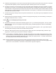
11. Install the large pulley end of one of the pulley racks (Figure A, Item 7) to the eccentric cap using a cotter pin (Figure A, Item 17). The 7 series gauge racks have three rollers and the 9 series has four rollers. 12. Using two additional cotter pins, connect both counterweights (Figure A, Item 10) to the second pulley rack. The counterweights attach to the two holes on the bracket sides adjacent to the smallest pulley. 13.
23. Remove the vice grips and electrical tape, and slowly allow the counterweight assembly to drop down in the gauge tube. Once the weight assembly is on the bottom of the tube and the tape is slack, thread the loose end of the tape through the short nipple on the tank top and fish this end out of the manhole access. 24. Fasten the tape clamp (Figure A, Item 3) to the float (Figure A, Item 2) using a cotter pin with a flat washer at the head of the probe.
35. Install the UV guard (Figure A, Item 23) over the probe cable and route the probe cable to the junction box. The spiral UV guard should completely cover the exposed yellow probe cable and protect it from sun exposure. 36. Complete connections to the tank gauge. See the original Tank Gauge installation instructions to facilitate connection and setup for your system.
Moormann ATG Interface Retrofits The steps below explain how to install the FFS Bulk/Stik aboveground tank gauge equipment to an existing Moormann gauge. Refer to Figure A and in the back of this manual for an assembly diagram. Programming Tip: Record the tank level reading from the Moormann gauge before proceeding. To maintain an accurate gauge reading, the tank should be idle during this retrofit process. 1. Remove the ¼" (6.
15. If the roller brackets are threaded properly, you will finish with the last roller on the bottom of the roller bracket attached to the eccentric cap. Continue from this roller to the counterweight assembly and align the cotter pin bracket end of the tape to the top ears on the roller bracket in the counterweight assembly. 16. Locate the magnet bracket (Figure A, Item 19).
Figure A 3 13 8 Float 18 14" Dia. x 3½" Thick (ref.) 7 22 23 4 Vertical Clearance Gauge Housing Base Support (customer supplied) Tank Roof Flange (customer supplied) 2" Tank Opening Pipe (customer supplied) 4 2" Pipe (galv.) (customer supplied) 21 20 11 10 7 19 9 1" Pipe (galv.) (customer supplied) 1" Union (galv.) (customer supplied) 1" Nipple (galv.) (customer supplied) .
©2006 FFS 000-2033 Rev.