
Operation Manual

Frama Matrix F22
12
2. Installation
It is easy enough to install the components yourself. Be sure to observe the safety instructions at all
times.
There are four steps to installation:
1. Assembly of the individual components
2. Registration with the FramaOnline2 system
3. Configuring the printer settings
4. Loading postage credit
2.1. General notes and safety information
Select a position near a mains socket and an Ethernet connection for your Frama Matrix franking
system. Avoid direct sunlight and severe vibration.
Draughts can affect the accuracy of the scales.
Your Frama Matrix franking system was manufactured for use in normal conditions. Remember:
Today’s furniture is coated with a confusing variety of paints, lacquers and synthetic materials. In
view of this, it is quite possible that some of these materials contain constituents which can attack or
soften the plastic feet of our equipment. The feet of our equipment, if affected by foreign
substances, can stain your furniture. Frama is unable to accept any liability in this respect for
obvious reasons.
With this in mind, use a non-slip underlay.
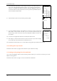
2.2. Making connections
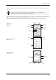
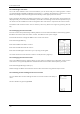
The figure below shows the location of the interfaces and the plug for the plug-in power supply unit
on the rear of the Matrix franking system's housing (connection panel).
Serial port
(RS232 – PC)
Scales
port
Socket for PSU
Communications
module